Magnetic detection circuit and encoder

a detection circuit and encoder technology, applied in the field of magnetic detection circuits, can solve the problems of significant obstacle to reducing detection circuit components cost, and high cost of magnetoresistive elements, so as to reduce the cost of encoders and reduce the number of expensive magnetoresistive elements for detection.

Inactive Publication Date: 2008-06-24
DR JOHANNES HEIDENHAIN GMBH
View PDF10 Cites 1 Cited by
  • Summary
  • Abstract
  • Description
  • Claims
  • Application Information

AI Technical Summary

Benefits of technology

[0012]An example embodiment of the present invention may provide a low-cost magnetic detection circuit, in which a differential detection function accomplished by outputting differential signals is not lost, and which may be less affected by temperature fluctuations and may be resistant to noise, and in which the number of magnetic detection elements may be reduced. An example embodiment of the present invention may provide an encoder, the cost of which may be further reduced by using such a magnetic detection circuit for a multi-revolution detection part, etc.
[0030]Since example embodiments of the present invention may allow the number of expensive magnetoresistive elements for detection to be reduced and also may allow a conventional differential input to be realized when signals are input into the comparator, a magnetic detection circuit, which is resistant to temperature changes and hardly affected by noise, may be provided without sacrificing the conventional differential detection function, and the use of this magnetic detection circuit may also allow the costs of an encoder to be reduced.

Problems solved by technology

Although magnetoresistive elements may be expensive, such a bridge circuit requires the use of two pairs of magnetoresistive elements.
Therefore, the detection circuit has component costs, which may represent a significant obstacle to reducing the cost of the encoder.

Method used


Image

  • Magnetic detection circuit and encoder
  • Magnetic detection circuit and encoder
  • Magnetic detection circuit and encoder

Examples


example embodiment 1

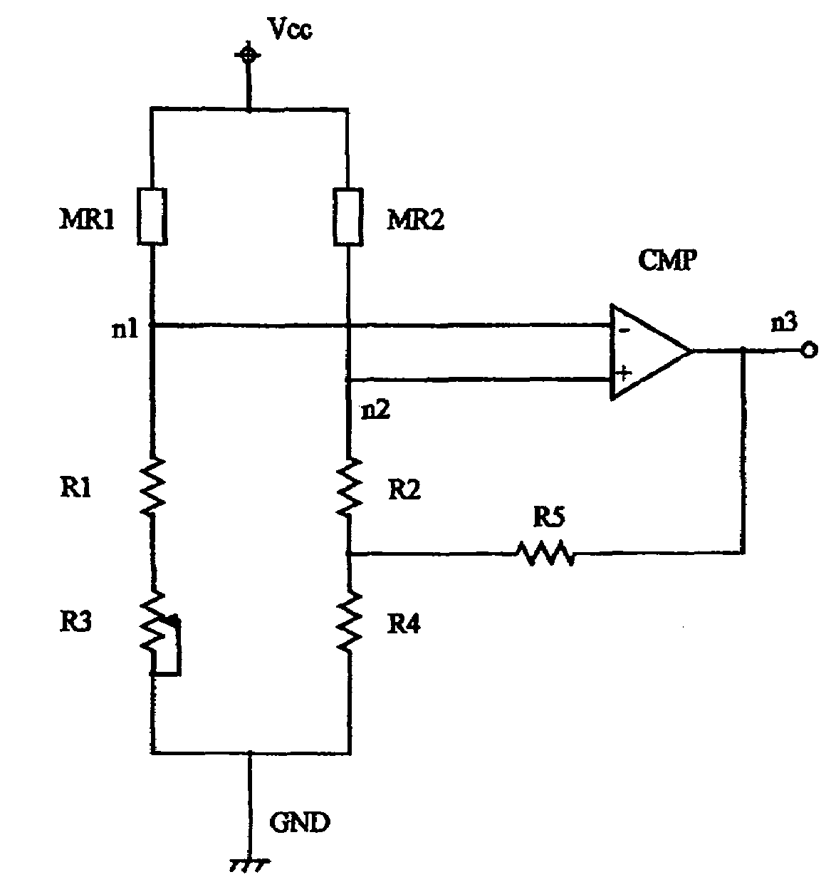
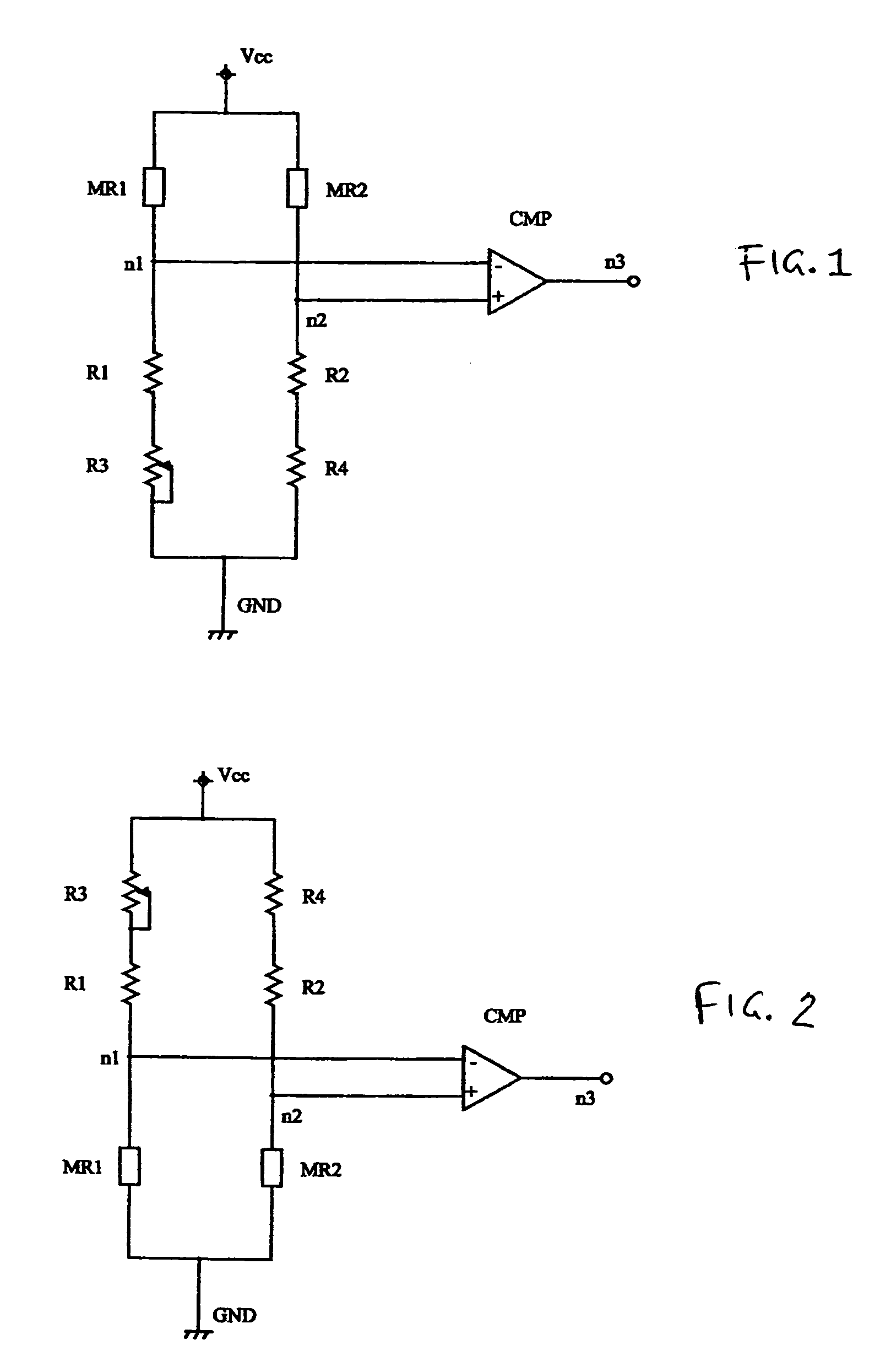
[0052]In the following, example embodiments of the present invention are explained with reference to the Figures. FIG. 1 is a circuit diagram, which illustrates a region of the magnetic detection part of an encoder having a magnetic detection circuit according to an example embodiment of the present invention. The circuit diagram illustrated in FIG. 1 is of a bridge circuit and a detection element arranged between current-source terminal Vcc and grounding terminal GND. Two bridge sections, a first bridge section and a second bridge section, are provided in this bridge circuit between the current-source terminal and the grounding terminal. The first bridge section has a first magnetic detection element MR1 of which one terminal is connected to the current-source terminal, a first fixed resistor R1 of which one terminal is connected to the other terminal of first magnetic detection element MR1, and an adjustable resistor R3 which is connected to the other terminal of first fixed resis...

example embodiment 2

[0063]FIG. 2 is a circuit diagram, which illustrates a region of the magnetic detection part of an encoder having a magnetic detection circuit according to an example embodiment of the present invention. In this example, the pair of magnetic detection elements MR1, MR2 is positioned closer to the grounding terminal than output-signal output points n1, n2. That is, the first bridge section has an adjustable resistor R3 of which one terminal is connected to the current-source terminal, a first fixed resistor R1 of which one terminal is connected to the other terminal of adjustable resistor R3, and a first magnetic detection element MR1 connected to the other terminal of first fixed resistor R1, while the second bridge section has a third fixed resistor R4 of which one terminal is connected to the current-source terminal, a second fixed resistor R2 of which one terminal is connected to the other terminal of third fixed resistor R4, and a second magnetic detection element MR2 connected ...


PUM


Abstract

To provide a low-cost magnetic detection circuit, in which the differential detection function accomplished by outputting differential signals may not be lost, and which may be hardly affected by temperature fluctuations and may be resistant to noise, and in which the number of magnetic detection elements may be reduced, and to provide an encoder, the costs of which may be further reduced by using such a magnetic detection circuit for the multi-revolution detection part, etc., a magnetic detection circuit includes a bridge circuit formed by two bridge sections between the current-source terminal and the grounding terminal. The first bridge section and the second bridge section of the bridge circuit include magnetic detection elements MR1, MR2, respectively, and, viewed from the output-signal output points, the magnetic detection elements MR1, MR2 in the two bridge sections are arranged on only one of the sides that include the current-source side and the grounding-terminal side. An encoder includes such a magnetic detection circuit.

Description

CROSS-REFERENCE TO RELATED APPLICATIONS[0001]The present application claims priority to Application No. 2004-073328 filed in Japan on Mar. 15, 2004, which is expressly incorporated herein in its entirety by reference thereto.FIELD OF THE INVENTION[0002]The present invention relates to a magnetic detection circuit, which may detect changes in magnetism and convert them into electrical signals. The present invention also relates to an encoder, which is a device that includes such a magnetic detection circuit, is attached to the rotor or rotating body of an engine, motor, etc., or to an object to be measured that is moving in a straight line, and determines the degree of positional displacement of the object to be measured, e.g., the number of revolutions and / or the angle of rotation or the movement position or the degree of movement.BACKGROUND INFORMATION[0003]There are many devices in which a magnetic detection circuit is used. Among these, coding devices, from which high precision a...

Claims


Application Information

Patent Timeline
Patent Type & Authority Patents(United States)
IPC IPC(8): G01B7/30G01B7/00G01B7/14G01D5/16G01D5/245G01R17/00G01R33/09
CPCB82Y25/00G01D5/145G01R33/093
Inventor HAGA, HIROSHIYAMASHITA, MAMORU
Owner DR JOHANNES HEIDENHAIN GMBH
Why Eureka
Try Eureka