
System and method for synchronizing link state databases in a network environment

a network environment and database technology, applied in the field of communication, can solve the problems of cumbersome information exchange, arduous propagation and processing of such signaling data, and the network architecture has grown increasingly complex in the communication environment, so as to achieve the effect of minimal overhead, avoid modification of packet formats or route calculation mechanisms, and save resources

Active Publication Date: 2008-06-24
CISCO TECH INC
View PDF45 Cites 37 Cited by
  • Summary
  • Abstract
  • Description
  • Claims
  • Application Information

AI Technical Summary

Benefits of technology

The present invention provides an improved communication approach that minimizes information exchanges in packet communications to achieve optimal synchronization of link state databases. The method involves communicating summary updates between network elements to achieve adjacency between them. The technical effects of this approach include reducing the amount of signaling data exchanged between network elements, minimizing network overhead, conserving resources, and reducing network traffic. The invention is flexible and allows for complete information exchange or a given network device's needs. It also allows for optimal timing and battery consumption.

Problems solved by technology

Networking architectures have grown increasingly complex in communication environments.
However, as network systems become more sophisticated, this information exchange may become cumbersome.
As a result, the propagation and processing of such signaling data can be arduous.
Moreover, in virtually all networking architectures, speed is a critical issue.
The exchange of signaling data generally slows communication speeds and inhibits system performance.
In certain cases, signaling data may be exchanged and then quickly become obsolete, as a given network element disappears (e.g. fails or gets removed from the network).
Thus, the ability to offer a system or a protocol that effectively synchronizes existing network elements (without hindering system speeds, taxing processing capabilities of network components, or exchanging a large amount of data that could be irrelevant later) provides a significant challenge to network designers, component manufacturers, and system administrators.

Method used


Image

  • System and method for synchronizing link state databases in a network environment
  • System and method for synchronizing link state databases in a network environment
  • System and method for synchronizing link state databases in a network environment

Examples


Embodiment Construction

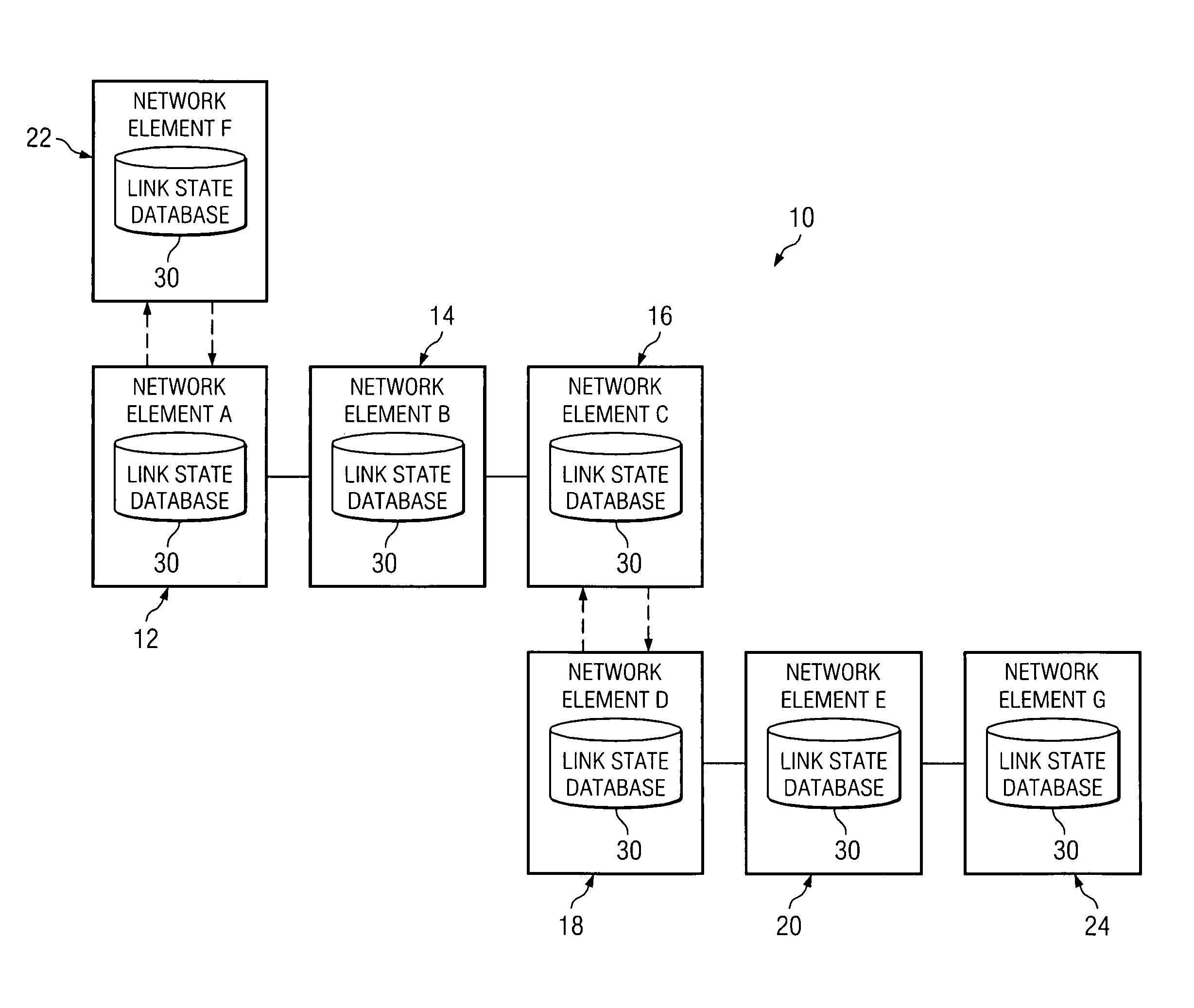
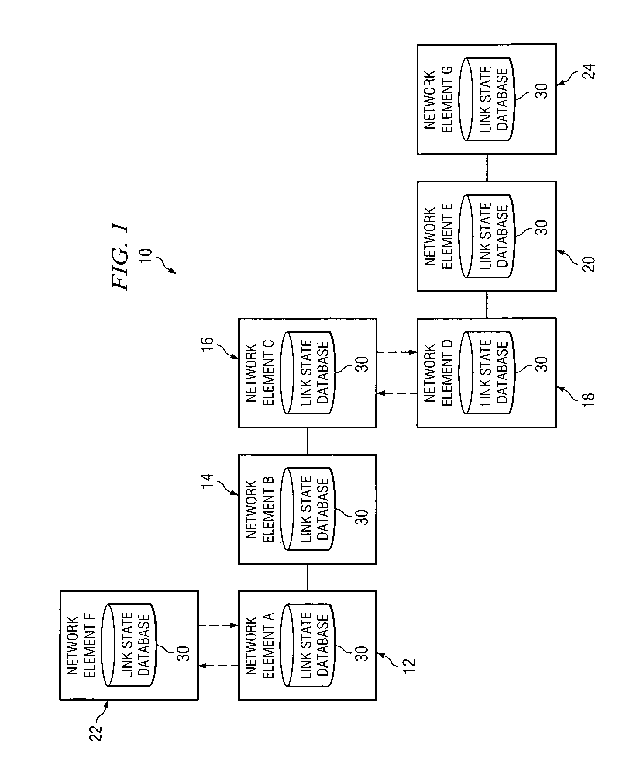
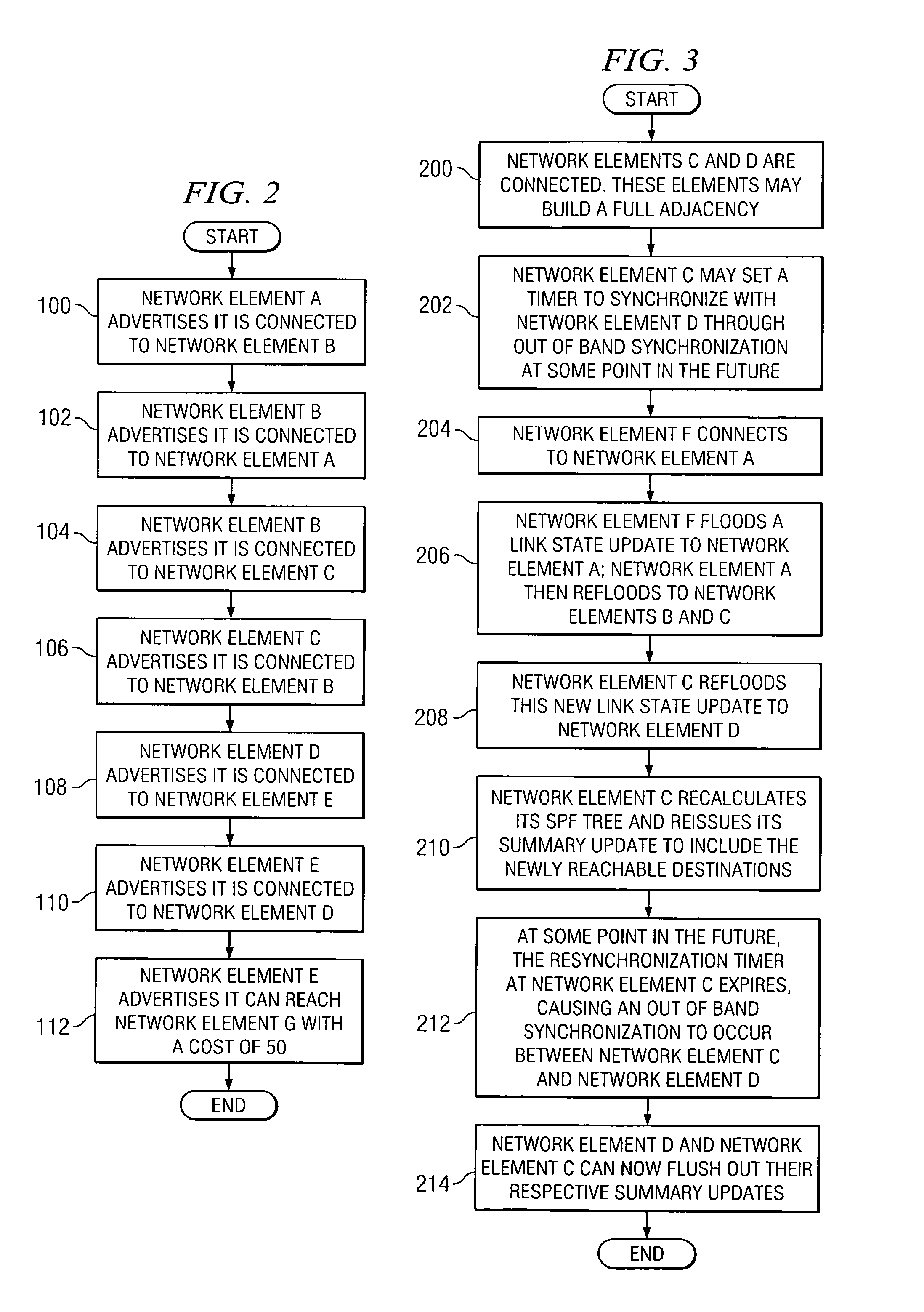
[0016]FIG. 1 is a simplified block diagram of a communication system 10 for synchronizing link state database information in a network environment. Communication system 10 may include multiple network elements 12, 14, 16, 18, 20, and 22. Network elements 12, 14, 16, 18, 20, and 22 may also be referred to herein as network elements A-F respectively. The letter designations assigned to network elements 12, 14, 16, 18, 20, and 22 do not connote any type of hierarchy; the designations are arbitrary and have been used for purposes of teaching only. These designations should not be construed in any way to limit their capabilities, functionalities, or applications in the potential environments that may benefit from the features of communication system 10. Each network element 12, 14, 16, 18, 20, and 22 may be equipped with a link state database 30 that includes information associated with surrounding network elements, as well as data to be used in routing packets in the context of network ...


PUM


Abstract

A method for communicating packets in a network environment is provided that includes communicating, by a first network element, a first summary update to a second network element. The method further includes receiving a second summary update from the second network element. The exchange of the first and second summary updates achieves adjacency between the first and second network elements. The first and second summary updates include, at least, locally generated state information and a single link state.

Description

TECHNICAL FIELD OF THE INVENTION[0001]This invention relates in general to the field of communications and, more particularly, to a system and a method for synchronizing link state databases in a network environment.BACKGROUND OF THE INVENTION[0002]Networking architectures have grown increasingly complex in communication environments. This complexity has resulted in numerous protocols being implemented in order to ensure that network elements are aware of their surroundings and to direct packets in an efficient manner. For example, certain network elements may exchange packets in order to indicate to each other the absence or presence of an adjacent network element or to provide routing updates. In this manner, neighbors are able to become aware of their surroundings and direct or manage traffic properly.[0003]The signaling data that gets passed between network elements is crucial for effective routing of information or data. The signaling data serves as a basis for an effective syn...

Claims


Application Information

Patent Timeline
Patent Type & Authority Patents(United States)
IPC IPC(8): G01R31/08H04J3/06
CPCH04L45/021G06F17/30575G06F16/27
Inventor CHANDRA, MADHAVI W.COOK, DAVID A.RETANA, ALVARO E.WHITE, RUSSELL I.YANG, YI
Owner CISCO TECH INC
Learn More