Calibration methods and structures in wireless communications systems

Active Publication Date: 2008-06-24
CALLAHAN CELLULAR L L C
View PDF38 Cites 234 Cited by
  • Summary
  • Abstract
  • Description
  • Claims
  • Application Information

AI Technical Summary

Benefits of technology

[0012]The present invention is directed to wireless transceiver calibration methods and structures that compensate across a signal bandwidth for relative gain and

Problems solved by technology

Performance of modern wireless communications equipment is typically limited by three factors: power & bandwidth, interference, and the wireless channel itself.
For example, the Federal Communications Commission has imposed power and bandwidth limitations on most communications bands (e.g., the 2.4 GHz ISM and the 5 GHz UNII bands) and these limitations limit the range and data rate of associated devices.
Accordingly, systems that employ conventional modem and signal processing technologies may not be able to support future multimedia and other high data rate applications (e.g., streaming video).
In unlicensed communications bands, interference is a serious problem since multiple emitters may share the same frequency in an uncontrolled manner.
Interfe

Method used


Image

  • Calibration methods and structures in wireless communications systems
  • Calibration methods and structures in wireless communications systems
  • Calibration methods and structures in wireless communications systems

Examples


embodiment 200

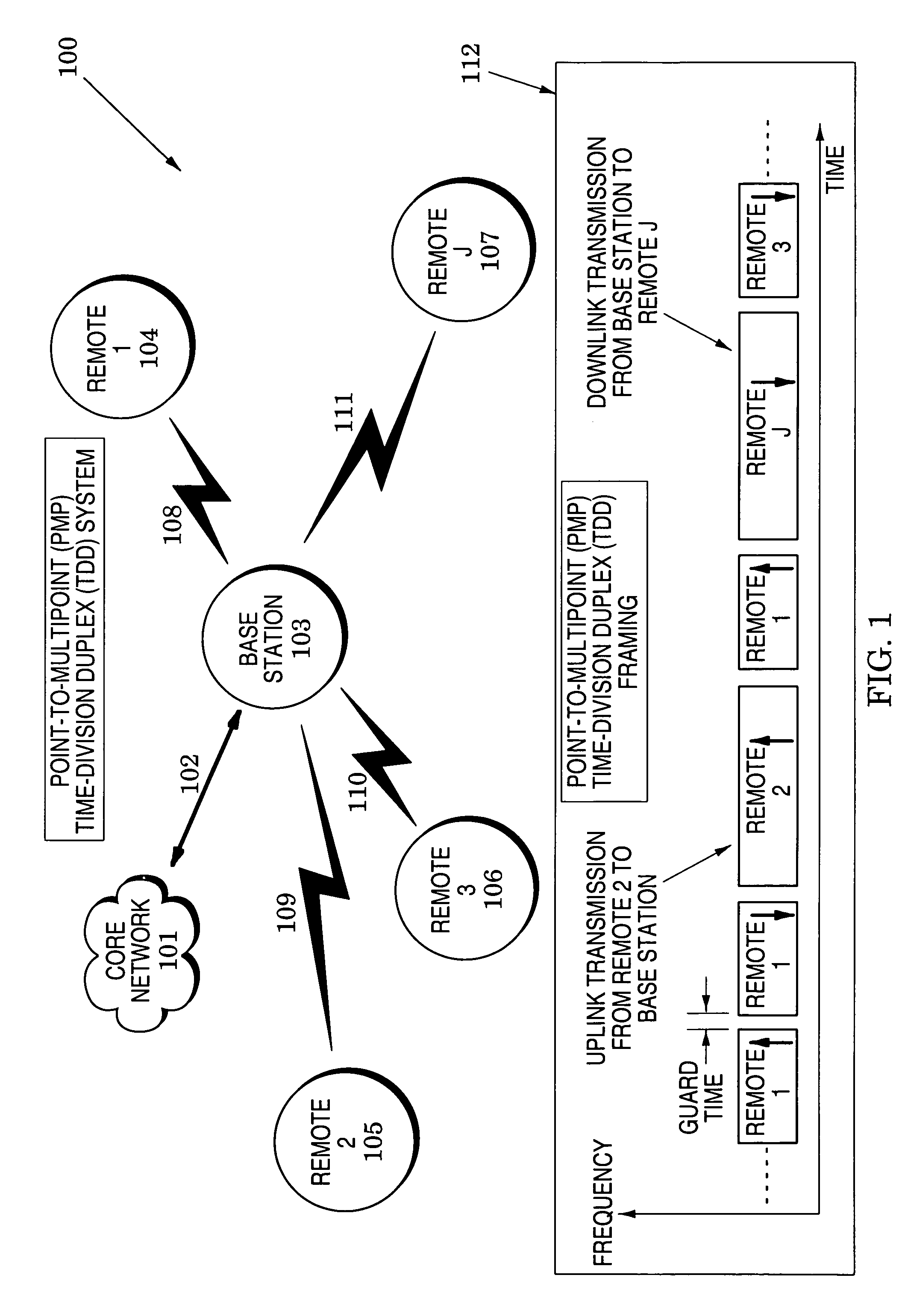
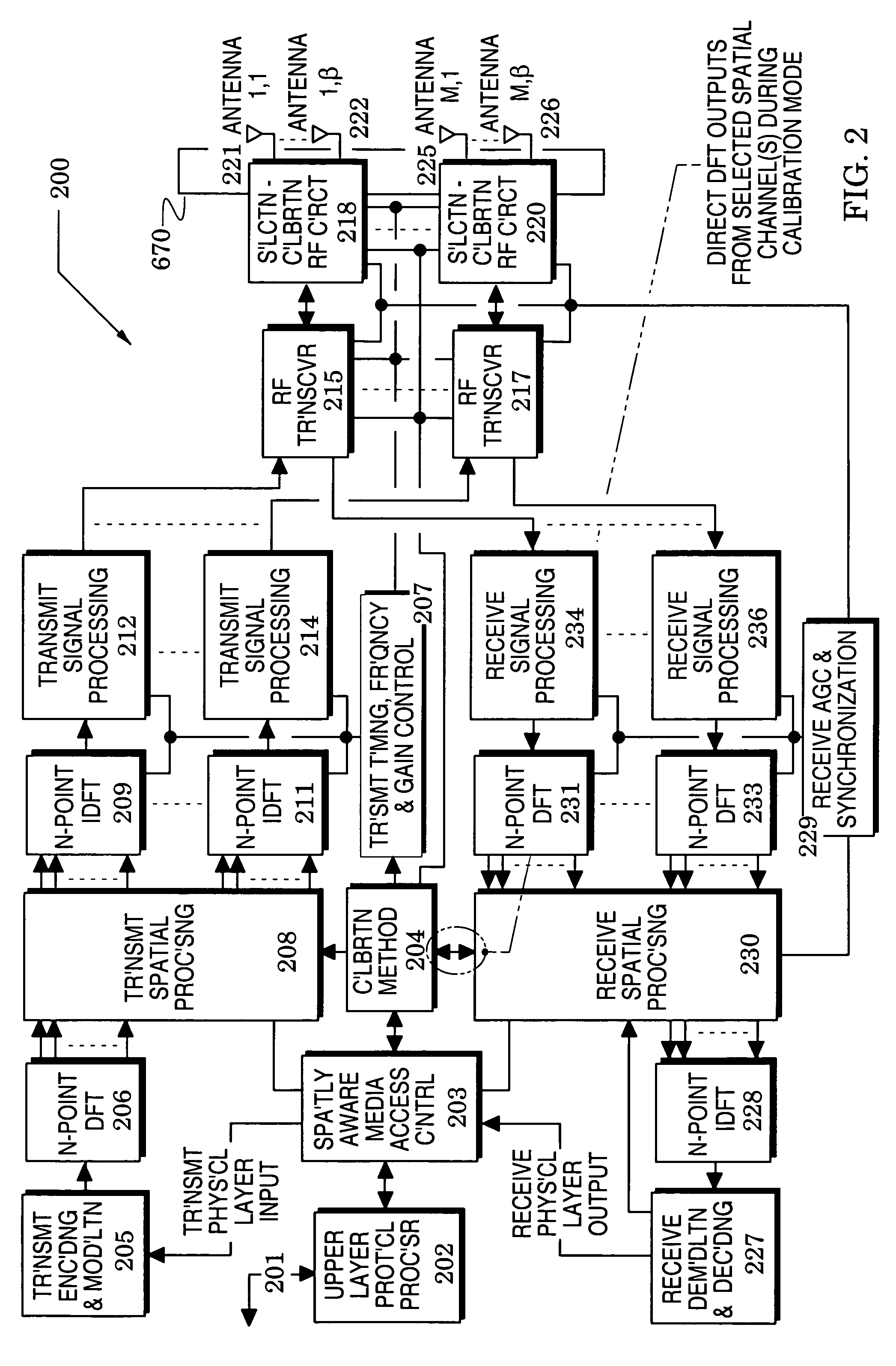
[0024]The present invention is particularly directed to wireless communications devices which may be advantageously used, for example, in the communications system 100 of FIG. 1. An embodiment 200 of a wireless communications device of the invention is shown in FIG. 2 and a flow chart 300 of FIG. 3 illustrates basic calibration processes in this unit. To enhance understanding of the processes of the flow chart 300, its description is preceded below with an examination of the elements of the system of FIG. 1 and the unit of FIG. 2. Receive and transmit processing details of the wireless communications device 200 are then described with reference to FIGS. 4 and 5.

[0025]Subsequently, a calibration structure embodiment is described with reference to FIG. 6 and the following description of FIG. 7 examines exemplary calibration processes that are realized with the calibration structure. Finally, a description of FIGS. 8-10 discloses OFDM transmission, reception and calibration signals tha...

first embodiment

[0070]The determination of the factor αRX2(f) depends on the type of receive spatial processing algorithm and how it processes differential errors between spatial channels. This factor may be dynamic, based on whether the receive subsystem is thermal or quantization noise limited, for example. As in the first embodiment, the calibration coefficients for other spatial channels may be obtained by replacing “2” in the above equations with the spatial channel number (1 through M).

[0071]The calculated calibration coefficients are then applied in process step 306 of FIG. 3 and as further described below with reference to functions of the transmit spatial processing 208 and the receive spatial processing 230. After this application, elapsed time is measured in process step 307 and compared to a calibration interval threshold in decision 308.

[0072]When decision 308 determines that the elapsed time exceeds the calibration interval threshold, the method monitors the status of the communicatio...

embodiment 400

[0074]FIG. 4 illustrates an embodiment 400 of the receive spatial processing 230 of FIG. 2 wherein DFTs 231-233 and the calibration method 204 were introduced in FIG. 2 and a time index for frequency domain signals nTDFT is not shown for the sake of clarity.

[0075]The frequency domain signals from each receive spatial processing channel 1 through M are, optionally, compensated for frequency error by frequency offset correction (freq'ncy offset corr'ctn) 401-403 (under control of the receive AGC and synchronization 229 of FIG. 2). This function is optional since in some embodiments it is possible to correct for frequency error prior to the DFT operations.

[0076]The source of the frequency offset may, for example, be RF local oscillator differences, sampling frequency errors, or other implementation-related factors. Frequency offset correction 401-403 is preferably capable (with any of various frequency-correction methods) of correcting for a different frequency offset on each DFT outpu...


PUM


Abstract

Calibration methods and structures are provided for wireless communications devices that compensate across a signal bandwidth for relative gain and phase errors between spatial communication channels while utilizing existing transceiver structures and facilitating the use of frequency-domain spatial processing. The methods and structures are directed to time-division duplex (TDD) systems, and are particularly suited to those that incorporate orthogonal frequency division multiplexing (OFDM).

Description

CROSS REFERENCES TO RELATED APPLICATIONS[0001]This application claims the benefit of U.S. Provisional Application Ser. No. 60 / 447,791 filed Feb. 14, 2003.BACKGROUND OF THE INVENTION[0002]1. Field of the Invention[0003]The present invention relates generally to wireless communications systems and more particularly, to calibration methods and structures in such systems.[0004]2. Description of the Related Art[0005]Performance of modern wireless communications equipment is typically limited by three factors: power & bandwidth, interference, and the wireless channel itself.[0006]For example, the Federal Communications Commission has imposed power and bandwidth limitations on most communications bands (e.g., the 2.4 GHz ISM and the 5 GHz UNII bands) and these limitations limit the range and data rate of associated devices. Accordingly, systems that employ conventional modem and signal processing technologies may not be able to support future multimedia and other high data rate application...

Claims


Application Information

Patent Timeline
IPC IPC(8): H04B17/00
CPCH04B17/21H04B7/06H04B7/0825
Inventor FARLOW, CHARLES S.BOSCH, DONALD M.KROENKE, RANDALL A.LOUGHRAN, STEVEN J.
Owner CALLAHAN CELLULAR L L C
Why Eureka
Try Eureka