

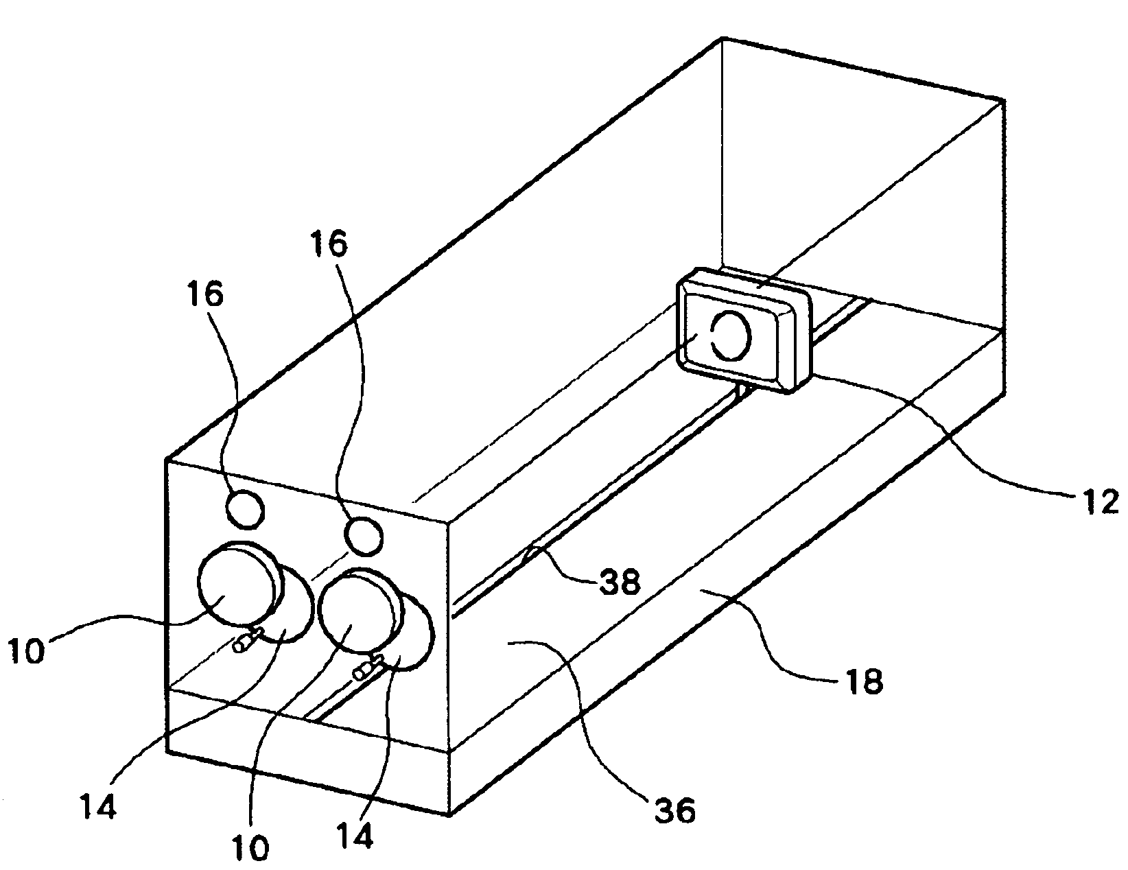
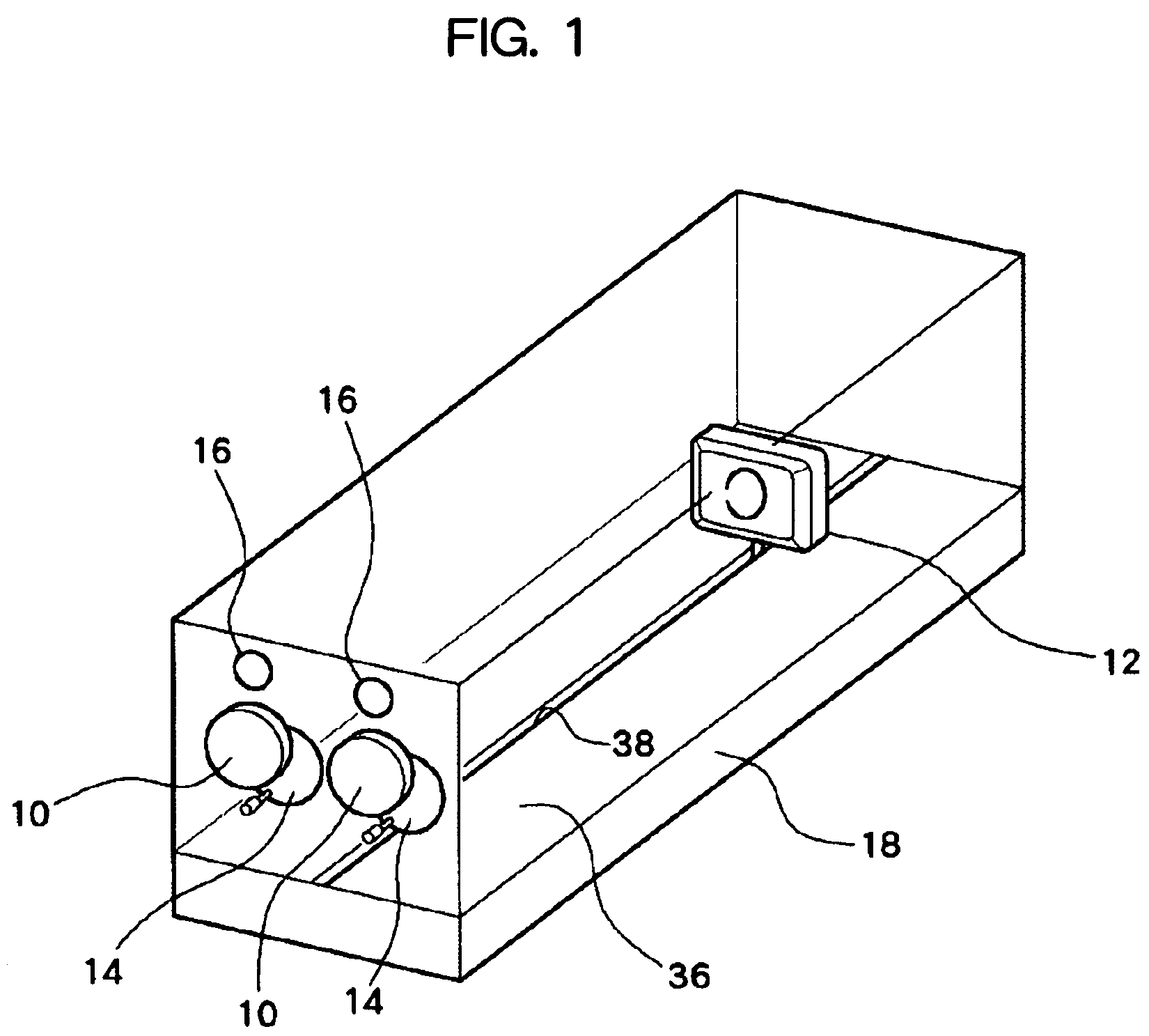
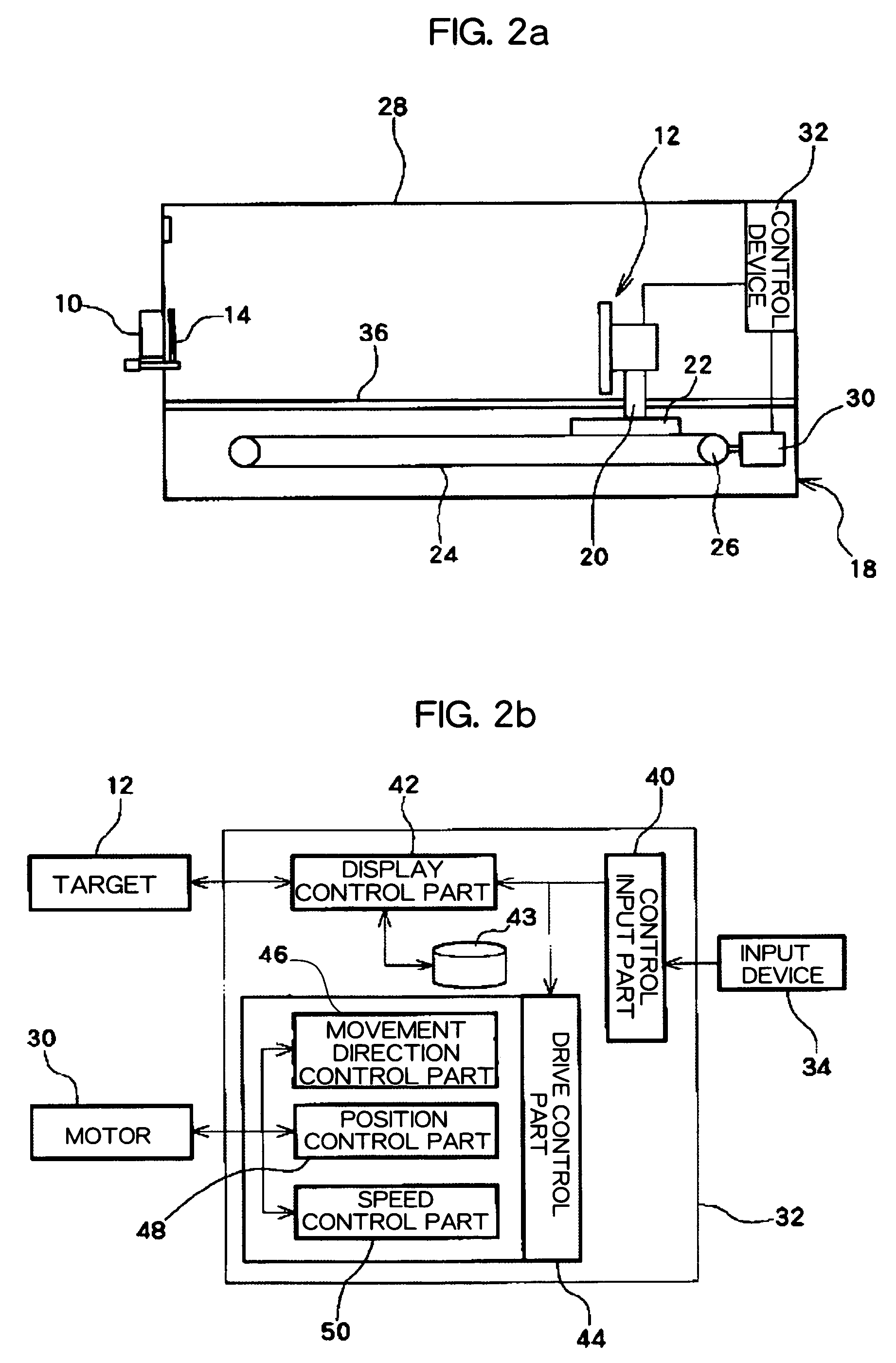
Eyesight improving device
a technology for improving eyesight and eyeglasses, applied in the field of eyeglasses, can solve the problems of increasing the amount of information sent to the brain, difficult to clearly see, and difficult to bring the mark into focus, and achieve the effect of convenient us
- Summary
- Abstract
- Description
- Claims
- Application Information
AI Technical Summary
Benefits of technology
Problems solved by technology
Method used
Image

Examples
example
[0063]Hereinafter, results of a vision improvement test carried out using the eyesight improving device of the embodiment will be described.
[0064]The eyesight improving device of the embodiment was used, and the following vision restoration training was carried out for 15 people in their teens, 23 people in their twenties, 25 people in their thirties, 14 people in their forties, and 16 people in their fifties.
[0065]Content of Training
[0066]The target 12 is reciprocated 15 times at a speed of 250 mm / second between a position where the distance between the eyepiece part 10 and the target 12 is 20 cm and a position where the distance is 65 cm, and the user focuses the eye on a white disk-shaped figure against the black background. The size of the figure is 80 mm in diameter at the far point (distance of 65 cm from the eyepiece part 10), and 24.6 mm in diameter at the near point (distance of 20 cm from the eyepiece part 10), and is linearly contracted or enlarged according to the distan...
PUM
 Abstract
Description
Claims
Application Information