
Film guide for a movie camera

a film guide and camera technology, applied in the field of film guides for movie cameras, can solve the problems of increased film transport resistance, noise, increased film channel and/or film gap size, etc., and achieve the effect of low production cost and wide tolerance requirements

Inactive Publication Date: 2008-07-01
ARNOLD & RICHTER CINE TECHN & BETRIEBS
View PDF6 Cites 5 Cited by
  • Summary
  • Abstract
  • Description
  • Claims
  • Application Information

AI Technical Summary

Benefits of technology

[0010]The solution according to the invention ensures that a constant parallel film channel and film gap, which can be preset, are maintained between the image window and the gripper platform and / or the spacing window of a movie camera, thus ensuring exact maintenance of a focusing plane on the one hand and of defined friction conditions on the other hand with wide tolerance requirements and correspondingly low production costs.
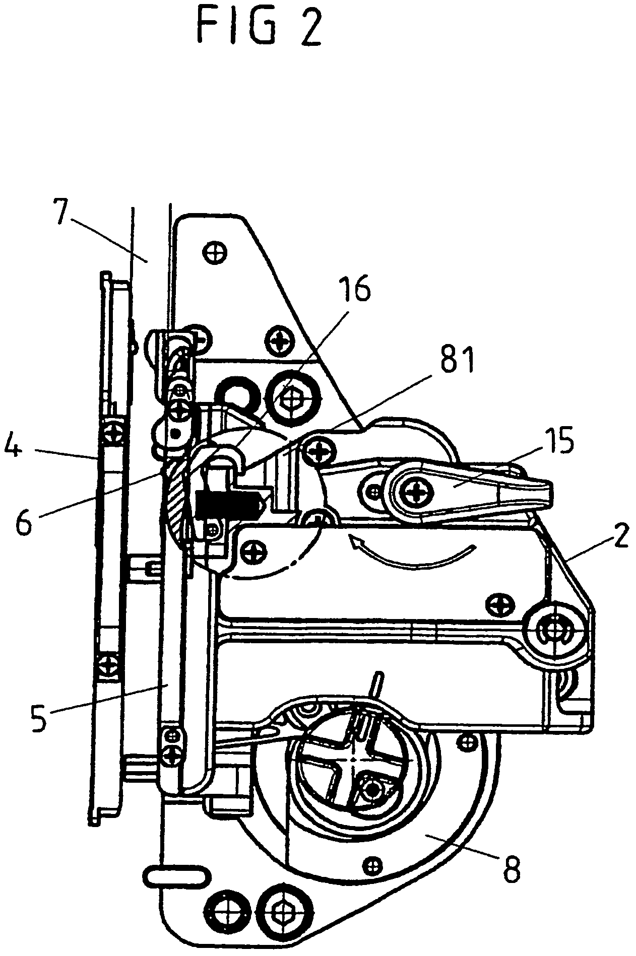
[0011]The solution according to the invention can be applied both to the film channel which is formed between the image window and the gripper platform and to the film gap which is formed between the image window and the spacing window. In this case, the size and parallelity of the film channel are governed exclusively by the support of the gripper platform on the image window, and the size and parallelity of the film gap are governed by the support of the spacing window on the image window, thus avoiding the dependency of the film channel on the support of the gripper platform by means of undefined contact surfaces on the image window, and the dependency of the film gap, which is formed between the spacing window and the image window, on the sprung connection of the spacing window to the gripper platform, so that the predetermined size and parallelity either of the film channel or of the film gap or of both the film channel and the film gap are ensured even during movement and / or pivoting of the gripper platform, which is connected to the drive module, for film insertion.
[0015]The support of the gripper platform and / or of the spacing window directly on the image window via the projections or webs and in particular via the three projections which are arranged at the corner points of an equilateral triangle results in the size and parallelity of the film channel and / or of the film gap being governed exclusively by the machining, which can be carried out very accurately, of a part of the gripper platform and / or of the spacing window, specifically by means of the projections.

Problems solved by technology

The film channel or film gap which is formed between the image window on the one hand and the gripper platform and the spacing window on the other hand is of such a size that, on the one hand, the focusing plane remains constant in the area of the image window section during exposure of the individual images of the movie film and, on the other hand, neither fluttering of the movie film nor increased friction between the movie film and the frame of the image window as well as of the film plane surface of the gripper platform and of the spacing window occurs, which would lead to noise, to damage to the movie film and to increased film transport resistance.
After movement or pivoting of the drive module for insertion of a movie film, this can lead, for example, to the size of the film channel and / or film gap being increased or decreased and to loss of parallelity between the opposite image planes of the image window and of the spacing window, so that the focusing plane is not ensured in all areas of the film channel and film gap, and / or excessive friction of the movie film occurs.

Method used


Image

  • Film guide for a movie camera
  • Film guide for a movie camera
  • Film guide for a movie camera

Examples


Embodiment Construction

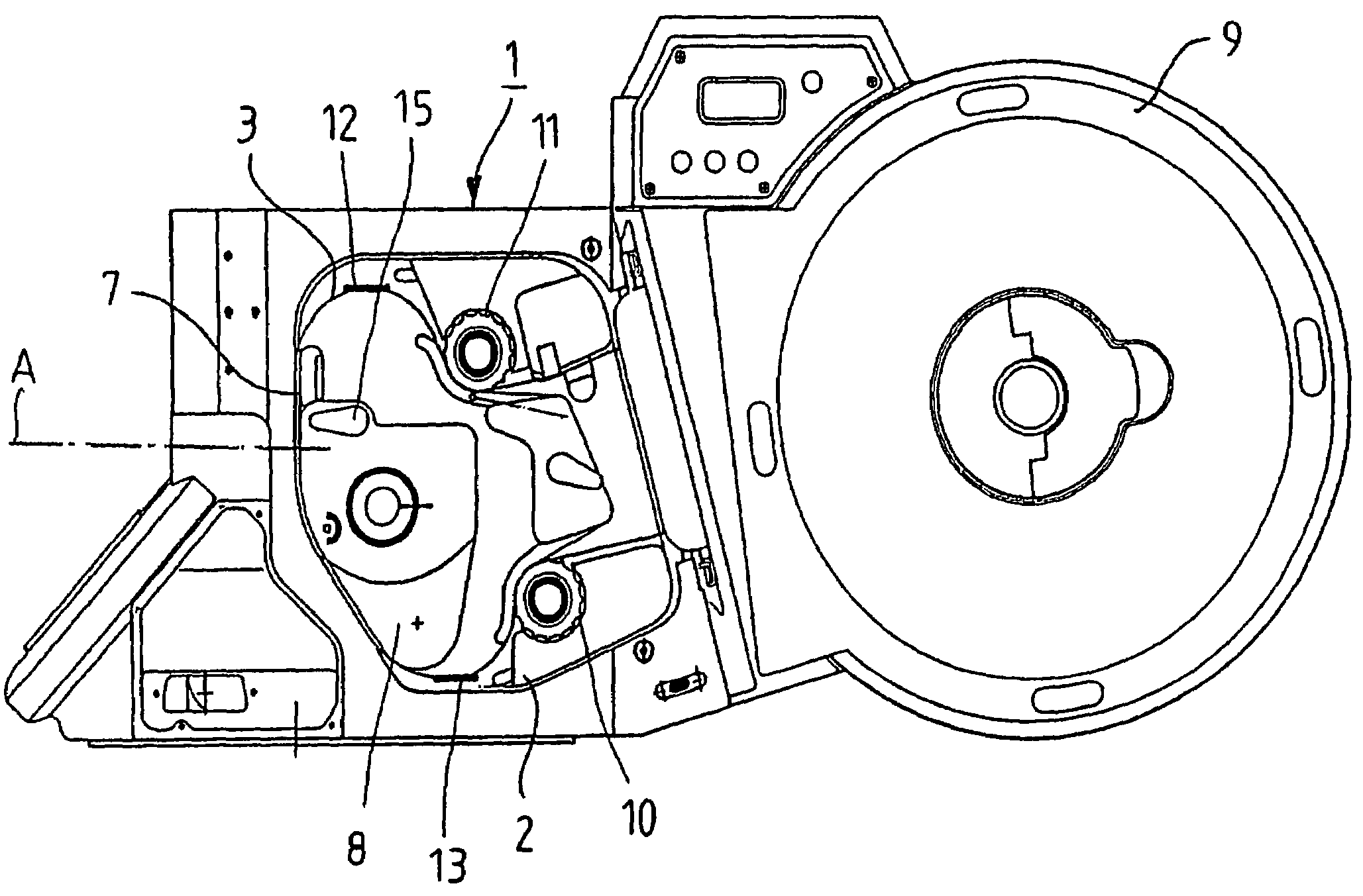
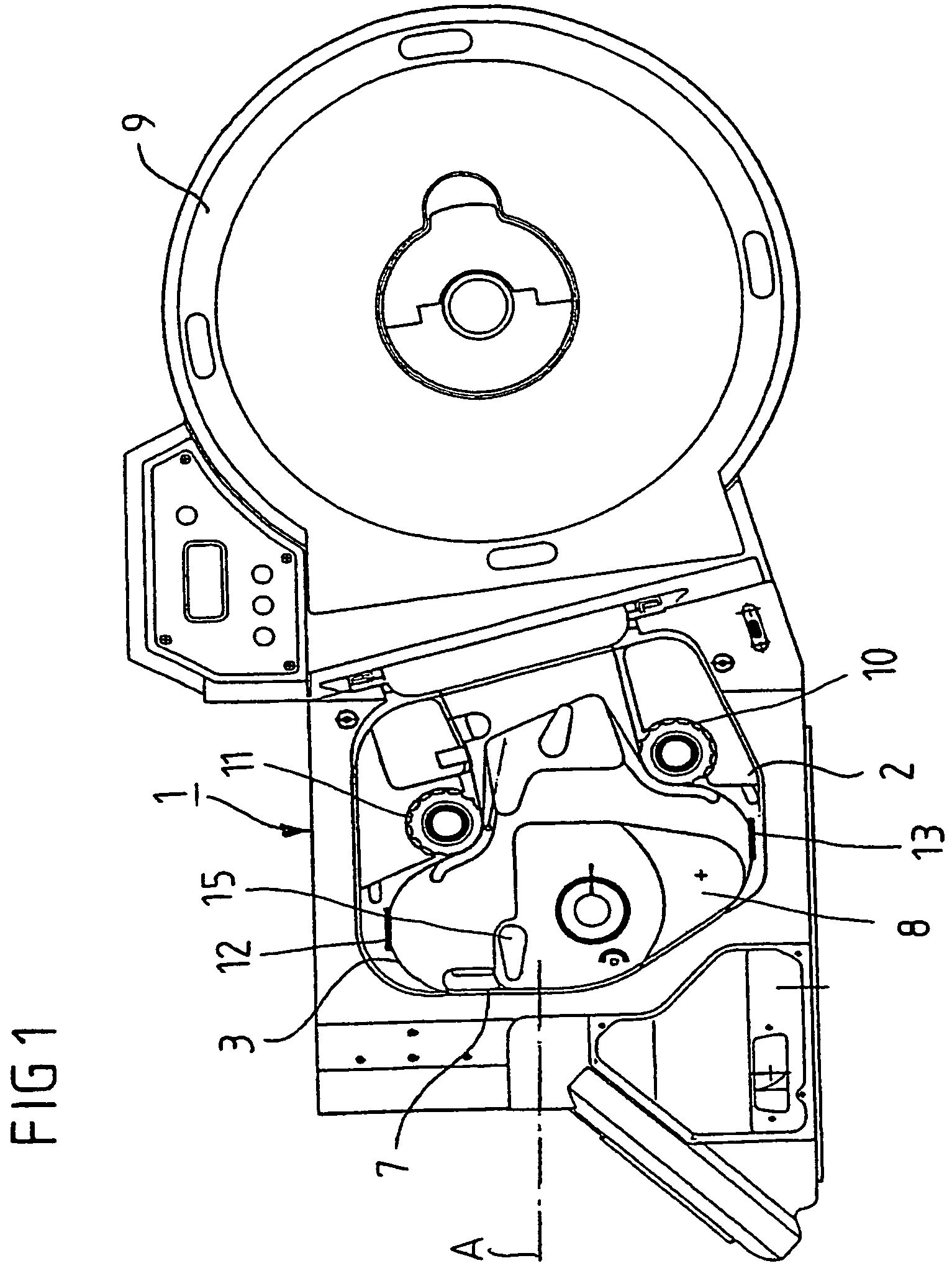
[0032]FIG. 1 shows a side view of a movie camera with a camera housing 1, with a film cassette 9 fitted, and with a film transport mechanism which is in the form of a drive module 2, with the camera door open. The film transport mechanism has a feed device 10 and a take-up device 11 for continuous film transport and in order to form film loops 12, 13 on both sides of an image window section, which is arranged in the recording beam path A, of an image window, and has a gripper mechanism 8 with a film transport motor, by means of which the movie film 3 is transported intermittently in a film guide. In the area of the recording beam path A, the film guide forms a film channel 7 between the image window, which is connected to the camera housing 1, and a gripper platform, which is connected to the drive module 2, of the gripper mechanism 8, which narrows to form a film gap in the area between the image window and a spacing window, which is connected to the gripper platform.

[0033]The movi...


PUM


Abstract

A film guide for a movie camera having an image window which is arranged in a recording beam path of the movie camera, a gripper platform which is supported on the image window, between whose mutually facing film planes a film channel is formed through which a movie film is moved by a film transport mechanism, and a spacing window which is connected to the gripper platform. The spacing window is supported on the image window in such a manner that the film channel narrows to form a film gap between the mutually facing film planes of the image window and the spacing window.

Description

CROSS-REFERENCE TO A RELATED APPLICATION[0001]This application is a National Phase Patent Application of International Patent Application Number PCT / DE2004 / 000555, filed on Mar. 11, 2004, which claims priority of International Patent Application Number PCT / DE2004 / 000237, filed on Feb. 04, 2004.BACKGROUND[0002]The invention relates to a film guide for a movie camera.[0003]In order to provide a film guide for movie films in movie cameras, an image window section of an image window is arranged in the optical beam path of the recording objective of the movie camera. The image window section defines the size of the area of the individual images of the movie film to be exposed. Herein, the film plane of the image window section is opposite the film plane of a gripper platform and of a spacing window being integrated in the gripper platform in such a way that, between the two film planes, a film channel is formed between the image window and the gripper platform. In this way, a film gap is...

Claims


Application Information

Patent Timeline
Patent Type & Authority Patents(United States)
IPC IPC(8): G03B1/48
CPCG03B19/18G03B1/50
Inventor BAUER, FRITZ GABRIELHANDLER, JOSEF
Owner ARNOLD & RICHTER CINE TECHN & BETRIEBS
Learn More