Architectures for external SATA-based flash memory devices

a flash memory device and architecture technology, applied in the direction of coupling device connection, electric discharge tube, instruments, etc., can solve the problems of exacerbated bottlenecks and limited top transfer rate of usb protocol (roughly 480 mbits/sec), and achieve the effect of facilitating the storage of data in semiconductor memory

Inactive Publication Date: 2008-07-01
SUPER TALENT TECH CORP
View PDF59 Cites 65 Cited by
  • Summary
  • Abstract
  • Description
  • Claims
  • Application Information

AI Technical Summary

Benefits of technology

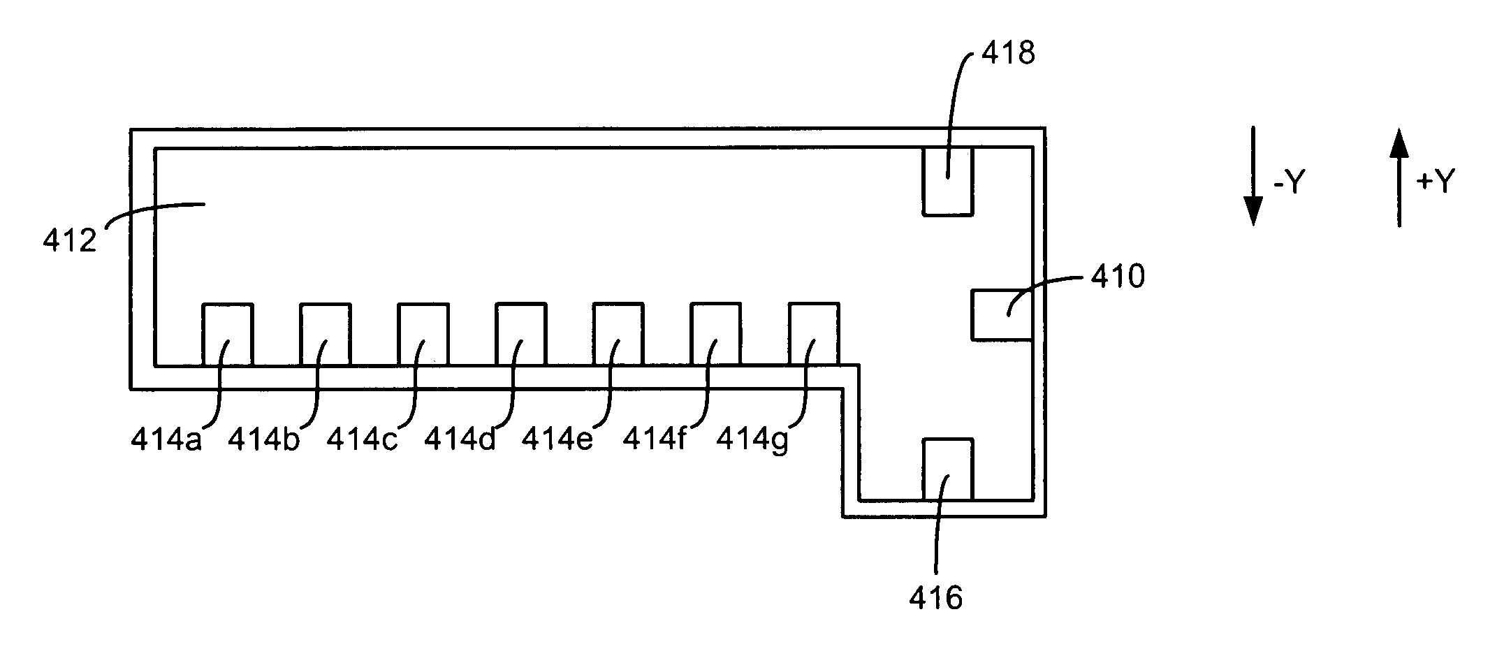
[0005]The invention relates, in an embodiment, to a Serial Advanced Technology Attachment-based (SATA-based) flash memory device configured for coupling with a host machine. The device includes semiconductor memory configured for storing data. The device further includes a plug having therein a plug cavity, the plug cavity having a generally L shape cavity for housing a set of SATA industry-standard signal pins in respective industry-standard positions with respect to the plug cavity, at least a subset of the set of SATA industry-standard signal pins being configured to carry address and data signals to facilitate storing the data in the semiconductor memory. The L shape cavity is characterized by a longer substantially rectangular cavity coupled with a shorter substantially rectangular cavity. The plug additionally has a set of power pins that includes at least a first power pin. The SATA-based flash memory device employs a SATA protocol for exchanging the data with the host machine using the set of SATA industry-standard signal pins, the SATA-based flash memory device obtaining power via the set of power pins.

Problems solved by technology

While the USB protocol is useful as protocol for transferring data to and from external memory devices, the limited top transfer rate of the USB protocol (roughly 480 Mbits / sec) has become a bottleneck in some situations due to simplex situation and the sharing of bandwidth by multiple USB devices.
This bottleneck is exacerbated as flash memory read / write throughput increases.

Method used


Image

  • Architectures for external SATA-based flash memory devices
  • Architectures for external SATA-based flash memory devices
  • Architectures for external SATA-based flash memory devices

Examples


Embodiment Construction

[0023]The present invention will now be described in detail with reference to a few embodiments thereof as illustrated in the accompanying drawings. In the following description, numerous specific details are set forth in order to provide a thorough understanding of the present invention. It will be apparent, however, to one skilled in the art, that the present invention may be practiced without some or all of these specific details. In other instances, well known process steps and / or structures have not been described in detail in order to not unnecessarily obscure the present invention.

[0024]Various embodiments are described herein below, including methods and techniques. It should be kept in mind that the invention might also cover articles of manufacture that includes a computer readable medium on which computer readable instructions for carrying out embodiments of the inventive technique are stored. The computer readable medium may include, for example, semiconductor, magnetic,...


PUM


Abstract

A Serial Advanced Technology Attachment-based (SATA-based) flash memory device configured for coupling with a host machine. The device includes semiconductor memory configured for storing data and a plug having therein a plug cavity, the plug cavity having a generally L shape cavity for housing a set of SATA industry-standard signal pins in respective industry-standard positions with respect to the plug cavity. The plug additionally has a set of power pins that includes at least a first power pin. The SATA-based flash memory device employs a SATA protocol for exchanging the data with the host machine using the set of SATA industry-standard signal pins, the SATA-based flash memory device obtaining power via the set of power pins.

Description

BACKGROUND OF THE INVENTION[0001]The present invention relates to an external Serial Advanced Technology Attachment-based (external SATA-based) flash memory device. More particularly, the present invention relates to a connector-powered flash memory device that can be connected to a host using the SATA protocol signals.[0002]External flash memory devices have been in use for some time. Generally speaking, a flash memory device employs semiconductor memory instead of a magnetic or optical disk to store data. Well known advantages offered by flash memory include higher performance, enhanced background erasing, buffering, and caching for I / O. Furthermore, flash memory has a high degree of reliability, requires lower power and in general involves less size and weight. Compared to magnetic-based or optical-based memory, flash memory is thought to offer better longevity through bad block management techniques, ECC (Error Correction Code), and wear leveling. Furthermore, flash memory is mo...

Claims


Application Information

Patent Timeline
Patent Type & Authority Patents(United States)
IPC IPC(8): H01R33/00
CPCG06F13/409H01R12/716H01R12/79G06F2213/0032
Inventor YU, I-KANGNI, JIMLEE, CHARLES C.
Owner SUPER TALENT TECH CORP
Why Eureka
Try Eureka