Multiple antenna system

a multi-antenna system and antenna technology, applied in multiplex communication, synchronisation arrangement, wireless communication, etc., can solve the problems of inability to measure delay at high precision, the main path of the test wave may happen to be blocked by obstacles, and the burden and cost of maintenance and control operations increase, so as to achieve accurate synchronization

Inactive Publication Date: 2008-07-01
FUJITSU LTD
View PDF11 Cites 97 Cited by
  • Summary
  • Abstract
  • Description
  • Claims
  • Application Information

AI Technical Summary

Benefits of technology

[0016]The present invention was conceived to overcome the above-described problems, and the present invention aims to accurately synchronize multiple antenna apparatuses in a multiple antenna system.
[0018]With this arrangement, antenna apparatuses connected to a base station apparatus can be accurately synchronized with each other in the multiple antenna system.

Problems solved by technology

Burden and cost of maintenance and control operations increase.
However, since the communication environment changes every moment, the main path of the test wave may happen to be blocked by obstacle.
Accordingly, the delay cannot always be measure at high precision.
However, this arrangement is unsuitable to an application of increasing the area size of each baseband processor, that is, an application where the number of the antenna units 104 is increased to expand the communicating space, while maintaining the number of users accommodated by the system (or the overall sectors).
This is because increasing the number of antenna units 104 to expand the communicating space results in excessive resources and processing capacity.

Method used


Image

  • Multiple antenna system
  • Multiple antenna system
  • Multiple antenna system

Examples


first embodiment

[0040]FIG. 3 is a schematic diagram of a communications system according to the invention. The system includes a center apparatus (base station apparatus) 302, and multiple antenna apparatuses (AU) 304, each antenna apparatus being provided in one of cells or sectors and connected to the center apparatus 302 via an associated optical cable 306. The center apparatus 302 is connected to a higher-layer apparatus or a network element (not shown) for controlling communication links. In this embodiment, the antenna apparatus 304 is placed in each cell to communicate with mobile devices (not shown) located in the cell.

[0041]FIG. 4 is a block diagram of the antenna apparatus 304. The antenna apparatus 304 comprises a wave division multiplex (WDM) filter 402, an optical-to-electric (O / E) converter 404, a serial-to-parallel (S / P) converter 406, a delay adjusting unit 408, a transmission unit 410, and a duplexer 412. The antenna apparatus 304 also comprises a receiving unit 414, a selector 416...

second embodiment

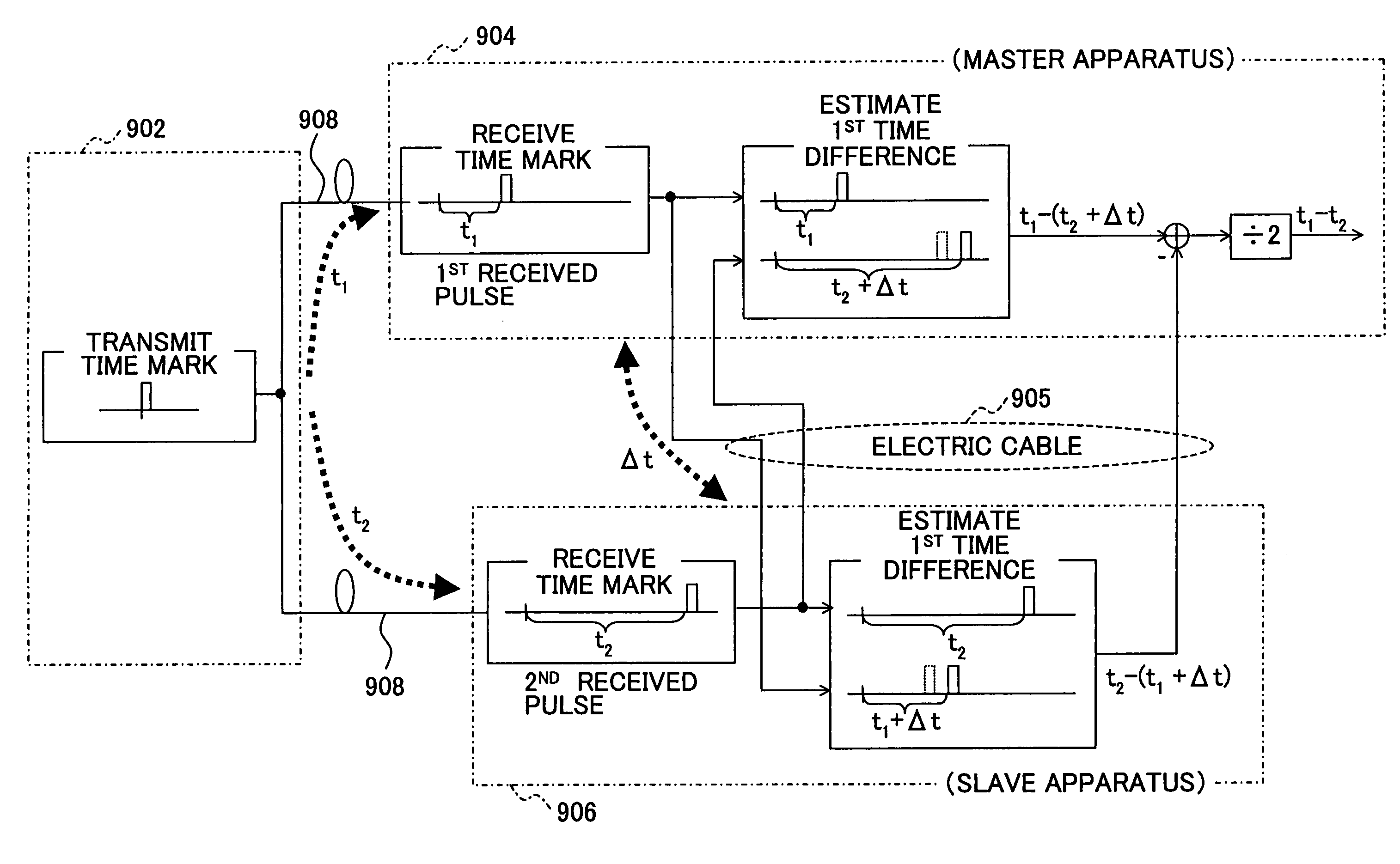
[0066]FIG. 9 is a schematic diagram of a communications system suitably applicable to an antenna diversity system according to the invention. The communication system includes a center apparatus (or a base station apparatus) 902, antenna apparatuses (AU) 904 and 906 provided in each cell or each sector, and optical cables 908 connecting the center apparatuses 902 and the antenna apparatuses 904 and 906. The antenna apparatuses 904 and 906 are connected to each other using an electric cable 905, which is capable of transmitting electric signals, in each cell. The center apparatus 902 is connected to a higher-layer control apparatus (or network component) that controls communication links. The antenna apparatuses 904 and 906 provided in each cell perform the antenna diversity technique to communicate with a mobile terminal (not shown) located in the cell.

[0067]FIG. 10 is a block diagram of the antenna apparatus 904 shown in FIG. 9. The antenna apparatus 904 has a similar structure to ...

third embodiment

[0086]FIG. 14 illustrates a center apparatus 1402 and an antenna apparatus 1404 according to the invention. In FIG. 14, only those components that are particularly relevant to this embodiment, and other components (such as transmit power amplifiers) are omitted. The configuration shown in FIG. 14 is directed to diversity transmission performed on downlink signals; however, the same applies to diversity receiving on uplink signals. In diversity receiving, synchronous detection (path estimation for rake receiving) has to be performed by the baseband processing unit at the symbol level, taking into account delay over the airways. In this embodiment, the center apparatus 1402 has a baseband (BB) processing unit 1406, a parallel-to-serial converter 1408, and an electric-to-optical converter 1410. The center apparatus 1402 is connected to the antenna apparatus 1404 via an optical cable 1403. The antenna apparatus 1404 has an optical-to-electric converter 1412 and a serial-to-parallel conv...


PUM


Abstract

A multiple-antenna system including a base station apparatus and a plurality of antenna apparatuses connected to the base station via optical cables is provided. The system comprises a first antenna apparatus and a second antenna apparatus connected to each other via an electric cable. Each of the first and second antenna apparatuses receives a reference pulse from the base station apparatus via the optical cables, and estimates a time difference between the received pulse and the reference pulse supplied from the counterpart antenna apparatus via the electric cable. At least one of the first and second antenna apparatuses adjusts signal transmission timing based on the time differences estimated by the first and second antenna apparatuses.

Description

BACKGROUND OF THE INVENTION[0001]1. Field of the Invention[0002]The present invention generally relates to a wireless communication technique, and more particularly to a multiple antenna system comprising a plurality of antenna devices, each being provided in one of multiple sectors, and a base station apparatus connected to the antenna devices via optical cables.[0003]2. Description of the Related Art[0004]In mobile communications systems, the space in which communication services are provided is divided into multiple cells or sectors, and wireless communication is carried out between mobile terminals located in certain sectors (or cells).[0005]FIG. 1 is a schematic diagram illustrating a part of a code division multiple access (CDMA) system, which is typically employed in the wireless communication field. Multiple antenna units (AU) 104 are connected to the base station apparatus 110 via associated signal converters 106 and optical cables 108. The base station apparatus 110 includ...

Claims


Application Information

Patent Timeline
Patent Type & Authority Patents(United States)
IPC IPC(8): H04L7/00H01Q3/26H04B7/06H04B7/08H04B7/26H04B10/00H04J3/06H04W16/28H04W56/00H04W88/08H04W92/00
CPCH04W88/08
Inventor FUNAKUBO, TOSHIAKISUNDEN, HIRONOBU
Owner FUJITSU LTD
Why Eureka
Try Eureka