Method for optimization of an order of component mounting, apparatus using the same, and mounter

a technology of component mounting and optimization method, which is applied in the direction of metal working apparatus, instruments, manufacturing tools, etc., can solve the problems of not always finding the optimal solution, taking a long time for optimization, and taking a lot of processing time to simultaneously, so as to achieve the optimal mounting order and shorten the time

Active Publication Date: 2008-07-01
PANASONIC CORP
View PDF11 Cites 18 Cited by
  • Summary
  • Abstract
  • Description
  • Claims
  • Application Information

AI Technical Summary

Benefits of technology

[0008]The present invention pertains to an optimizing method for an order of mounting components for a mounter equipped with a mounting head for picking up a plurality of components and mounting the components on a board, and aims to provide an optimizing method for a component mounting order based on which a more optimal mounting order can be searched within a shorter time.
[0012]The optimization is thus operated in consideration not only of the task number, as has been the conventional case, but also of the nozzle interchange time. The time required for interchanging the nozzles and executing the tasks, which takes a large proportion of the whole tact, is reduced and thereby the mounting time is shortened on the whole. Also, two parameters, the task number and the nozzle interchange time, are determined at the initial stage of the optimization so that the time required for searching an optimal mounting order is shortened.
[0014]Thus, a feasible solution is searched in ascending order of the task number so that the time necessary for optimization can be reduced.
[0016]Thus, the combination of the task numbers having high possibility to be a feasible solution is firstly searched and the search is also made for the decrease in the task number so that the more optimal solution (mounting order) can be found within a shorter time.
[0019]Thus, whether it is a feasible solution or not is examined repeatedly for the possible combinations of task numbers based on a round-robin search method. Therefore, a feasible solution can be found surely without missing the more optimal solution in spite that a longer search time is more or less required.
[0022]In order to achieve the above object, the inventors further focused on the nozzle interchange which makes up a large part of the whole tact. This has led to an invention of the algorithm for mounting all of the components without interchanging nozzles. In other words, an algorithm for determining one kind of nozzle set which enables the mounter to mount all the components with fewer task numbers is developed. As a result, in spite that the task number is incremented more or less by not performing nozzle interchange, it is conceivable that the mounting time on the whole does not increase greatly since the time previously taken by interchanging nozzles is completely omitted. After determining one kind of optimal nozzle set for optimization of the component mounting order, there is no longer any need to take nozzle interchange into account so that one optimization parameter is taken away and the time necessary for optimization processing on the whole is reduced. Moreover, a component or a control unit for nozzle interchange does not need to be incorporated in the mounter, that is to say, a component and lines on the mounting head are simplified and the period of time taken by producing the mounter is greatly reduced. The mounter with an extremely high value-performance ratio is thus realized.

Problems solved by technology

However, the above conventional optimization method takes a lot of processing time to simultaneously determine various conditions for optimization, such as: a Z-axis arrangement which is an array of component feeders to be set on a mounter; an arrangement of nozzles at a nozzle station; a nozzle pattern; and a mounting order (i.e., an order of mounting components in consideration of mounting points on a board).
Therefore, it is necessary to calculate a tact each time the nozzle pattern is changed and thereby it takes time for optimization.
It is also a problem that an optimal solution cannot always be found since a head position and a task and others of the line gang pickup head to be interchanged are determined using random numbers in order to change the conditions for optimization.

Method used


Image

  • Method for optimization of an order of component mounting, apparatus using the same, and mounter
  • Method for optimization of an order of component mounting, apparatus using the same, and mounter
  • Method for optimization of an order of component mounting, apparatus using the same, and mounter

Examples


first embodiment

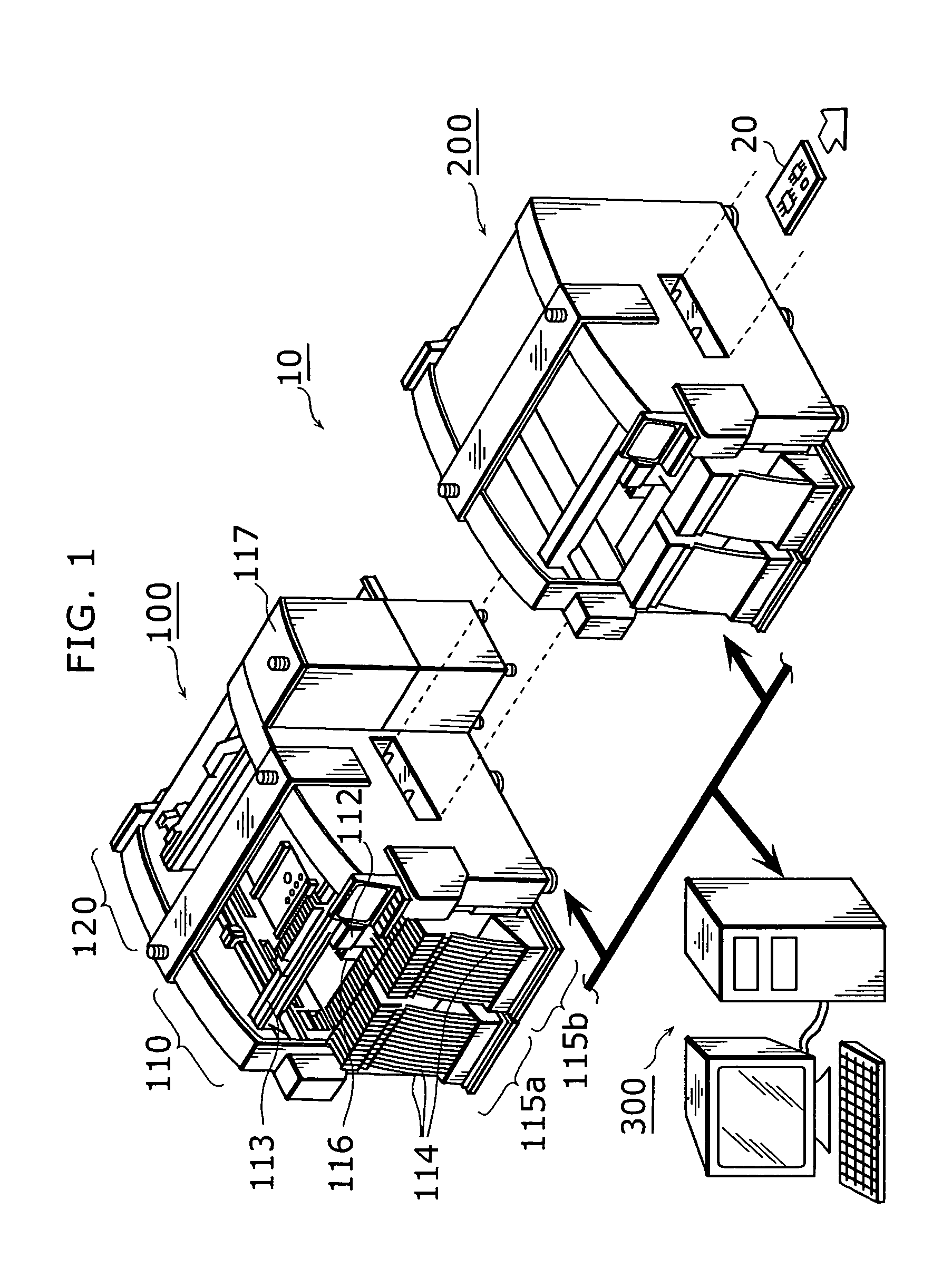
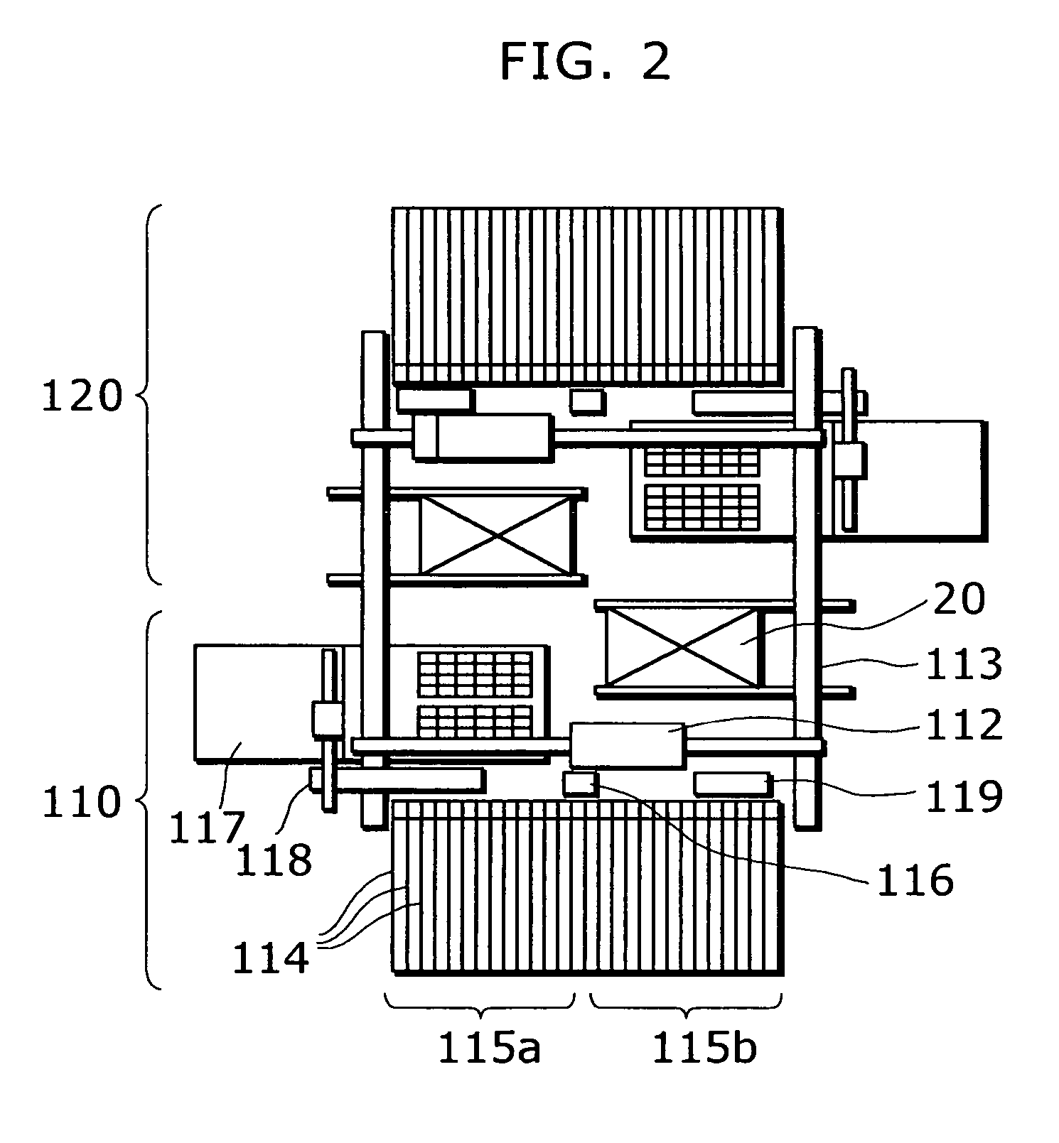
[0095]FIG. 6 is a block diagram showing the hardware construction of the optimization apparatus 300a that was shown in FIG. 1. In order to minimize the line tact time (the highest tact time out of the individual tact times of the stages forming the production line) for the mounting of components on a board, the optimization apparatus 300a determines which components should be mounted by each stage and the mounting order of components for each stage, based on information for all of the components that is provided by a component mounting CAD (Computer-Aided Design) apparatus or the like. By doing so, the optimization apparatus 300a produces optimal NC data. The optimization apparatus 300a includes a calculation control unit 301, a display unit 302, an input unit 303, a memory unit 304, an optimization program storing unit 305, a communication interface unit 306, and a database unit 307.

[0096]The optimization apparatus 300a is realized by having a standard computer system such as a per...

second embodiment

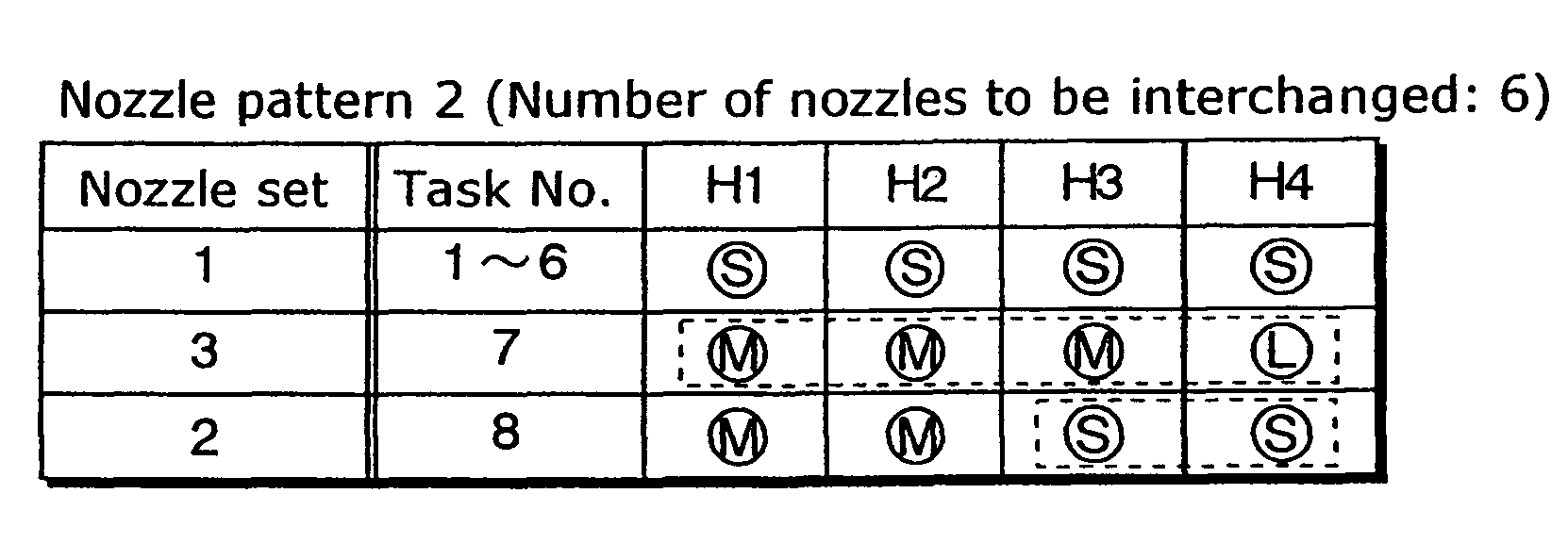
[0244]Next, the optimization apparatus according to the second embodiment of the present invention will be explained. The optimization apparatus according to the present embodiment, differing from the optimization apparatus used in the first embodiment which determines the optimal nozzle set with the presupposition that the pickup nozzles can be interchanged, determines the nozzle set optimal for mounting components with the smallest task number and the task number then used, without interchanging pickup nozzles.

[0245]FIG. 37 is a block diagram showing the optimization apparatus 300b according to the second embodiment of the present invention, namely, a structural example of the optimization apparatus shown in FIG. 1. The optimization apparatus 300b is a computer apparatus for determining the order of mounting components to be mounted at each sub stage and the components at each sub stage for all the components provided by the component mounting CAD apparatus or the like so as to mi...


PUM

PropertyMeasurementUnit
widthaaaaaaaaaa
widthaaaaaaaaaa
heightsaaaaaaaaaa

Abstract

An optimizing apparatus for optimizing a mounter equipped with a line gang pickup head which picks up a plurality of components and mounts them on a board. The apparatus includes a nozzle set determination unit for determining a nozzle set which reduces a mounting time in view of a number of times interchanging pickup nozzles and a total task number necessary for mounting the plural components, a nozzle pattern determination unit for determining an optimal nozzle pattern as well as an arrangement of pickup nozzles (nozzle arrangement) at a nozzle station, based on the nozzle set determined by the nozzle set determination unit, and Z-axis arrangement / mounting order optimization unit for determining an array order of component feeders and a mounting order of components while maintaining the determined nozzle set and nozzle pattern.

Description

BACKGROUND OF THE INVENTION[0001]1. Field of the Invention[0002]The present invention relates to a method for determining the optimal order in which a mounter is to mount electronic components onto a board, such as a printed circuit board. In particular, the invention relates to the optimization of the order of component mounting for a mounter equipped with a line gang pickup head that picks up a plurality of components and mounts them onto the board.[0003]2. Background of the Related Art[0004]The order in which a mounter mounts electronic components on a board such as a printed circuit board is conventionally optimized to minimize a tact time (i.e., the time taken by mounting). Recently, with diversification of the types of electronic devices, there has been an increase in demand for a multi-functional mounter equipped with a line gang pickup head based on a method referred to as “gang pickup” of picking up a plurality of components and mounting them on a board. Thus, various types...

Claims


Application Information

Patent Timeline
Patent Type & Authority Patents(United States)
IPC IPC(8): H05K13/00H05K13/04H05K13/08
CPCH05K13/08H05K13/0404Y10T29/53174Y10T29/53178Y10T29/53191Y10T29/4913H05K13/085
Inventor YAMAZAKI, TAKUYAMAENISHI, YASUHIROYOSHIDA, IKUOYAMASAKI, AKIHITONISHIDA, HIROYOSHIKONISHI, CHIKASHIMATSUMOTO, MASAYA
Owner PANASONIC CORP
Why Eureka
Try Eureka