Environmentally controllable storage system

a storage system and environment control technology, applied in the field of storage systems, can solve the problems of preventing laboratory personnel from doing higher-level tasks, heavy and complex prior-art carousel storage devices, and wasting time and energy

Active Publication Date: 2008-07-01
SIMBIOTIX CONTROL
View PDF12 Cites 67 Cited by
  • Summary
  • Abstract
  • Description
  • Claims
  • Application Information

AI Technical Summary

Benefits of technology

[0021]According to yet another aspect of the present invention, the first, second, third and fourth electrical motors of each of said storage modules of the cluster and each of said one or more robotic means are in electronic communication with a CPU means programmed with control system software so as to bring each of said robotic means and each of said storage modules under the coordinated control of said CPU means so to form a modular on-line storage system of indefinite capacity, thereby substantially eliminating the need for a standalone off-line mass storage facility.

Problems solved by technology

As such, the processing bottleneck in high throughput automated laboratory screening and analysis systems utilizing microplates has shifted from delivery and retrieval of the microplates to and from the workstations of the system to delivery of the microplates from storage into the automated system.
Not only are such prior art carousel storage devices unduly heavy and complex, due in part to the separate mounting hardware typically used to provide for such releasable mounting of the nests, but they must additionally provide plate locators on the nests to positively locate the microplates relative to the nests for accurate robotic gripping.
Such work is not only tedious and time consuming, but keeps laboratory personnel from doing higher level tasks.
Moreover, failure to timely replenish the on-line storage facility from the off-line storage facility may result in costly shut-downs of the automated system due to lack of microplates for processing.
It should also be considered that microplates manually loaded into the on-line storage facility for subsequent processing by the automated system are more likely to be subject to sequencing errors (i.e., being mixed up in their order) than machine identified and loaded microplates.
Such sequencing errors can result in the samples contained within the microplates being improperly processed at the workstations of the system, as the position of each respective microplate within the system is based on the assumption that laboratory personnel initially set-up the on-line storage facility according to the worklist provided.
Thus, such sequencing errors of the microplates can have potentially dire consequences.
Additionally, manual movement of the microplates from the off-line storage facility and loading thereof into the on-line storage facility is subject to mishap (e.g., dropping of the microplates), with resultant loss of the samples contained within the microplates.
The above problems with prior art microplate storage facilities are compounded where the storage must be environmentally controlled, i.e., maintained at a temperature that is not ambient to the processing system.
In such cases, prior art environmentally controlled storage devices are severely limited for several additional reasons.
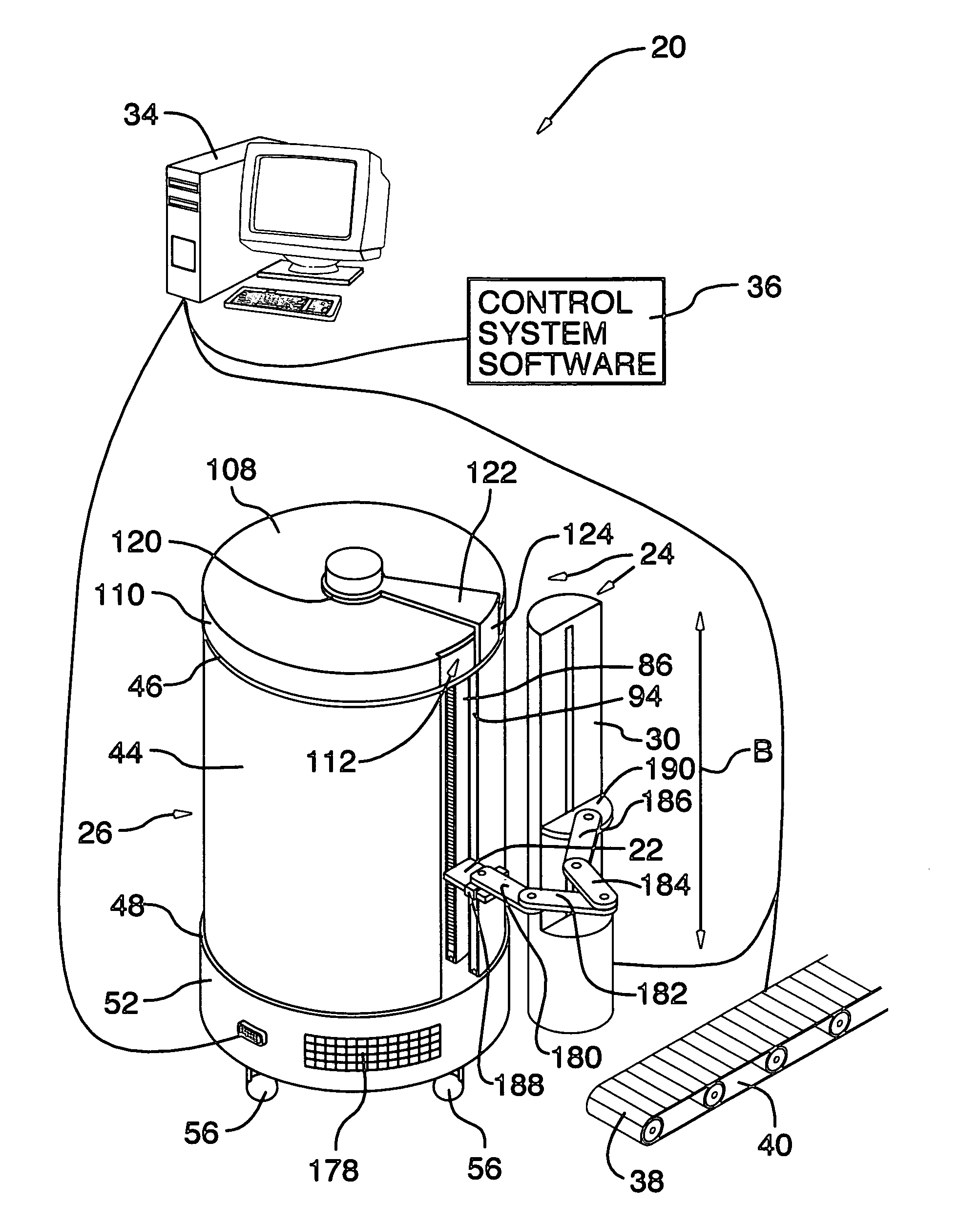
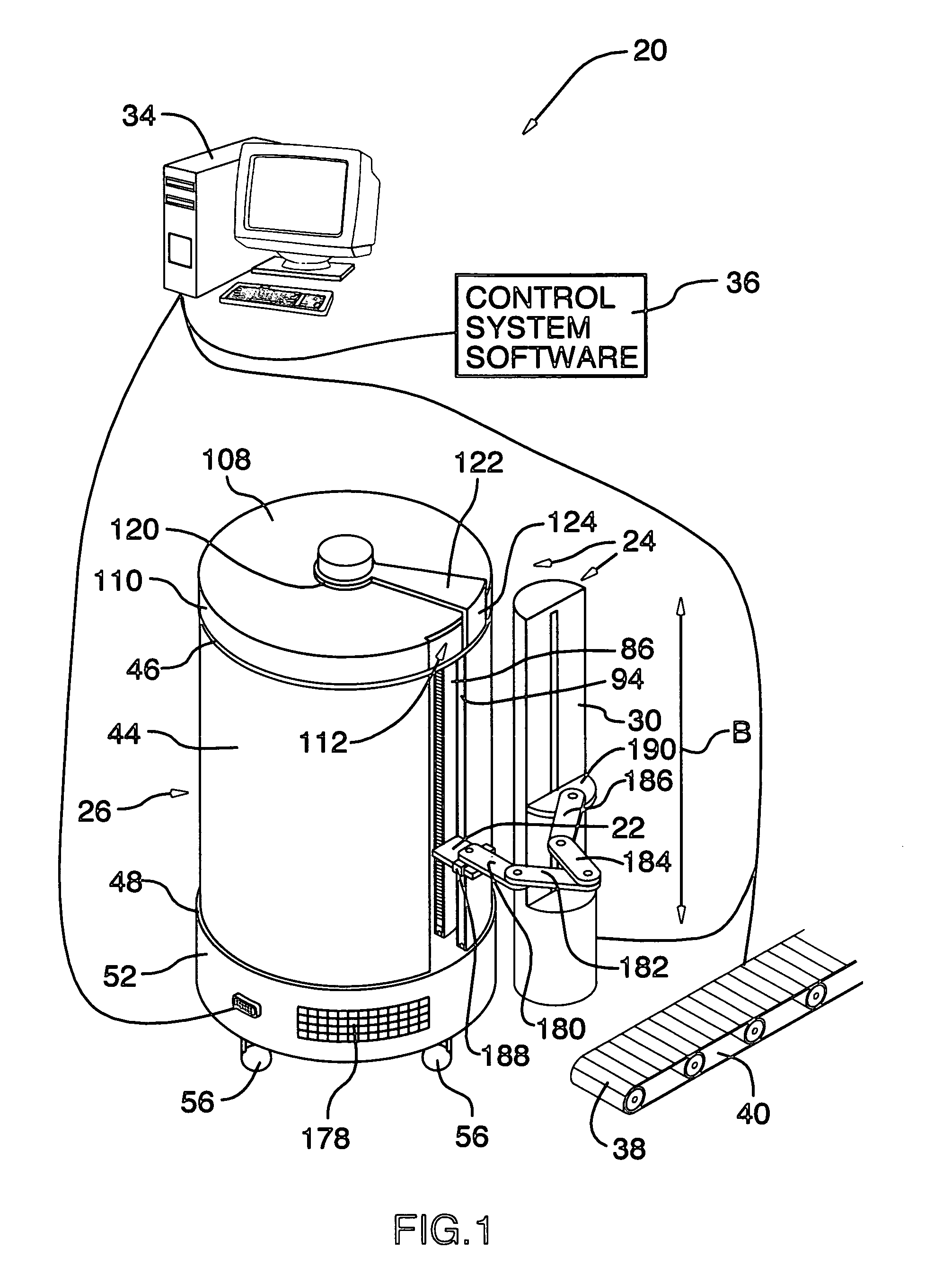
Moreover, the housing enclosure of such prior art environmentally controlled microplate storage devices have a single robotic arm positioned within the incubated housing enclosure, which robotic arm is limited in its operation to accessing only microplates stored in the carousel nest positioned immediately adjacent to the arm for delivery of such microplates to an area located immediately outside of a small door positioned in a front wall of the housing enclosure.
These structural arrangements significantly limit the available options for efficiently incorporating prior art types of environmentally controlled on-line laboratory storage facilities into high throughput automated microplate analysis systems.
Further, the placement of the robotic arm and its related equipment inside of an environmentally controlled housing enclosure introduces an extra heat load thereon and causes the robotic arm to operate in conditions of heat, cold, or humidity that may not be optimal to its performance, reliability or longevity.
Moreover, such an extra heat load may cause temperature variations in the microplates positioned in proximity to the robotics.
Such local temperature variations can cause undesirable effects on the sample characteristics, thus producing an uncontrolled basis of experimentation.
With respect to larger scale environmentally controlled off-line storage facilities, such as walk-up or walk-in refrigerators or incubators, the capacity of these units has to be planned for well in advance of their date of first use, and may often require facility restructuring, particularly in relation to any upsizing subsequent to initial facility construction.
Moreover, the capital costs associated with such off-line bulk microplate storage facilities are significant, further limiting their availability.

Method used


Image

  • Environmentally controllable storage system
  • Environmentally controllable storage system
  • Environmentally controllable storage system

Examples


Embodiment Construction

[0038]Referring to FIG. 1 of the drawings, there will be seen an automated laboratory analysis system 20 which is set up to conduct repetitive tests upon chemical or biological samples (not shown) contained in containers 22 stored in predetermined storage locations 28 (best seen in, for example FIGS. 3A through 3D)in a storage system 24 according to the invention. The containers are typically microplates 22 (that may take a number of known standardized configurations, including, without limitation, deep well microplates). Other types of labware of the same general configuration to the microplates 22 shown may be handled and stored in a manner analogous to that described hereinbelow with routine re-sizing of the necessary components of the invention, as will be readily apparent to those skilled in the art.

[0039]The storage system 24 illustrated in the embodiment of FIGS. 1 through 7D comprises a single storage module 26 and a single robotic means 30. This is for ease of illustration,...


PUM


Abstract

A storage system having one or more storage modules each comprising a substantially cylindrical housing having a curved sidewall portion extending between a top wall portion and a bottom wall portion, with the housing being disposed about a central axis. A carousel is mounted within the housing for controlled rotation about the central axis. The carousel has a plurality of storage locations disposed in vertical arrays about the axis to receive articles to be stored. A first door opening is formed in the sidewall portion to provide for access from the exterior of the housing to at least one of the vertical arrays adjacent to the first door opening. A means for controlling the temperature within the housing is also provided.

Description

FIELD OF THE INVENTION[0001]The present invention relates to storage systems for articles such as microplates, and more particularly to a storage system comprising one or more storage modules each having a controlled internal environment from which said articles may be removed and returned robotically.BACKGROUND OF THE INVENTION[0002]Medical, chemical and biological laboratories utilize large volumes of microplates and related labware in their drug development and analytical programs, whether for the analysis of chemical or biological samples. To be cost effective, for tracking accuracy, and for reasons of health and safety, most modern high throughput laboratory analysis systems are automated, with extensive use being made of conveyors, robots, and other microplate handling devices integrated into the system to provide for rapid mechanical movement of the microplates in seriatim through a sequence of workstations, such workstations including, without limitation, plate de-lidders, p...

Claims


Application Information

Patent Timeline
Patent Type & Authority Patents(United States)
IPC IPC(8): B65G1/00G06F7/00
CPCG01N35/028G01N2035/00356G01N2035/0463G01N2035/0425G01N2035/042
Inventor LOWE, GREGORY EARL
Owner SIMBIOTIX CONTROL
Why Eureka
Try Eureka