
Loaded weight measurement method and loaded weight measurement device for dump truck

a technology for loading weight measurement and dump trucks, which is applied in the direction of weighing auxiliary devices, instruments, transportation and packaging, etc., can solve the problems of vehicle body swaying significantly, no consideration is given to timing, and no guarantee of stable sta

Inactive Publication Date: 2008-07-01
KOMATSU LTD
View PDF8 Cites 13 Cited by
  • Summary
  • Abstract
  • Description
  • Claims
  • Application Information

AI Technical Summary

Benefits of technology

Enables accurate measurement of cargo weight in various work statuses, improving operational monitoring and efficiency by allowing selection of suitable measurement timing based on the truck's environment, thereby enhancing the reliability of weight measurements.

Problems solved by technology

However, in this prior art technology, no consideration is given to the timing at which the loaded weight is measured, and hence the measurement timing is fixed.
However, there is no guarantee that the state is always stable during transportation, and depending on the work site, there may be cases where the truck has to travel along very rough roads having an extremely uneven road surface.
When a truck is traveling along rough roads of this kind, the vehicle body sways significantly, and it is difficult to measure the transported weight accurately.
In particular, articulated type dump trucks which have swingably coupled front and rear vehicle bodies are often used in sites having rough terrain, such as mines, and hence they are subject to severe swaying during travel.
Therefore, cases may arise where the transported weight cannot be measured accurately during travel.

Method used


Image

  • Loaded weight measurement method and loaded weight measurement device for dump truck
  • Loaded weight measurement method and loaded weight measurement device for dump truck
  • Loaded weight measurement method and loaded weight measurement device for dump truck

Examples


first embodiment

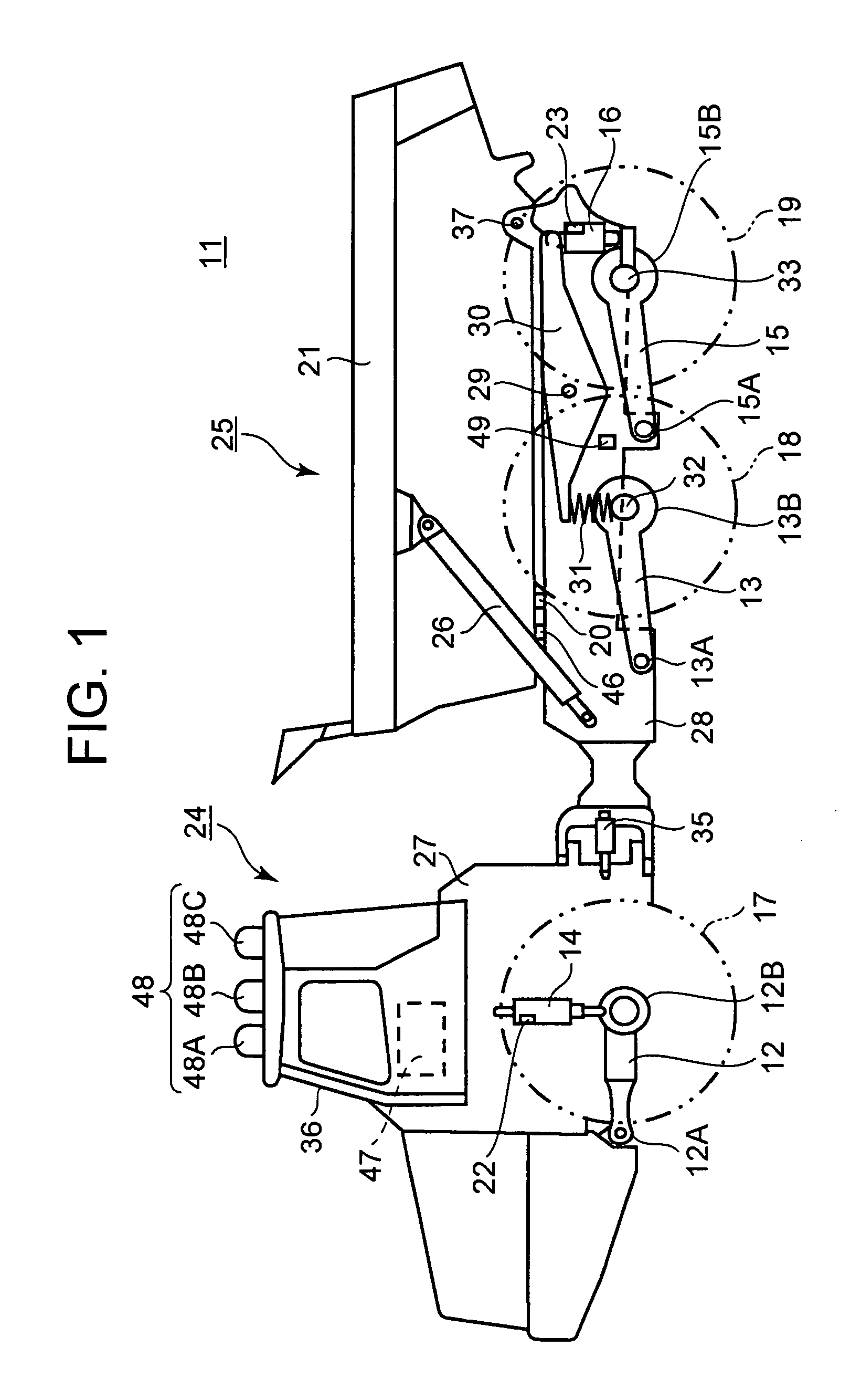
[0036]A first embodiment of the present invention will be described with reference to FIG. 1-FIG. 11. FIG. 1 is a side view of an articulated type dump truck 11.

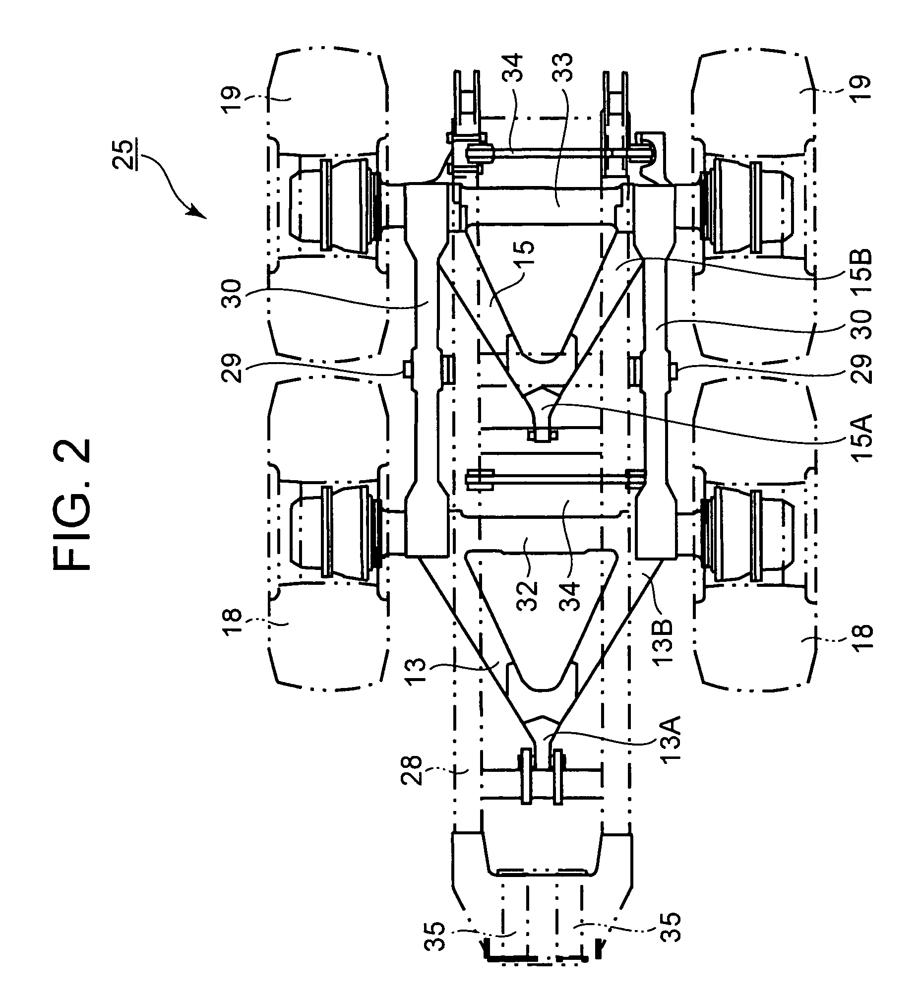
[0037]As shown in FIG. 1, the dump truck 11 comprises a front vehicle body 24 disposed on the front side and a rear vehicle body 25 disposed on the rear side. The front vehicle body 24 is supported by means of a front frame 27 and the rear vehicle body 25 is supported by means of a rear frame 28. The rear frame 28 is coupled bendably and swingably with respect to the front frame 27. An driver's cabin 36 is mounted on the front frame 27.

[0038]A left and right-hand pair of steering cylinders 35, 35 are provided spanning between the front frame 27 and the rear frame 28. By respectively extending or contracting the steering cylinders 35, 35, the rear frame 28 can be made to turn with respect to the front frame 27, and hence a steering operation can be performed.

[0039]A vessel 21 for loading a cargo, such as sand, for example, is...

second embodiment

[0187]Next, a second embodiment will be described on the basis of FIG. 12. In this embodiment, a limit switch 50 is provided in order to detect whether or not the equalizer bar 30 is abutted against the stopper 51.

[0188]FIG. 12 is a side view showing an enlargement of the region of an equalizer bar. In this embodiment, a limit switch 50 is provided in order to detect whether or not the equalizer bar 30 is abutted against a stopper 51. Respective limit switches 50 may be provided on the side of each stopper 51. Alternatively, limit switches 50 may be provided respectively on bases 52. The signals from the limit switches 50 are input to the controller 47.

[0189]The limit switch 50 may be constituted by a mechanical type limit switch in which an internal switch is actuated by the extension or contraction of a plunger, for example. Alternatively, for example, it may also be constituted by a proximity switch which detects the proximity of a physical body on the basis of change in a high-f...


PUM


Abstract

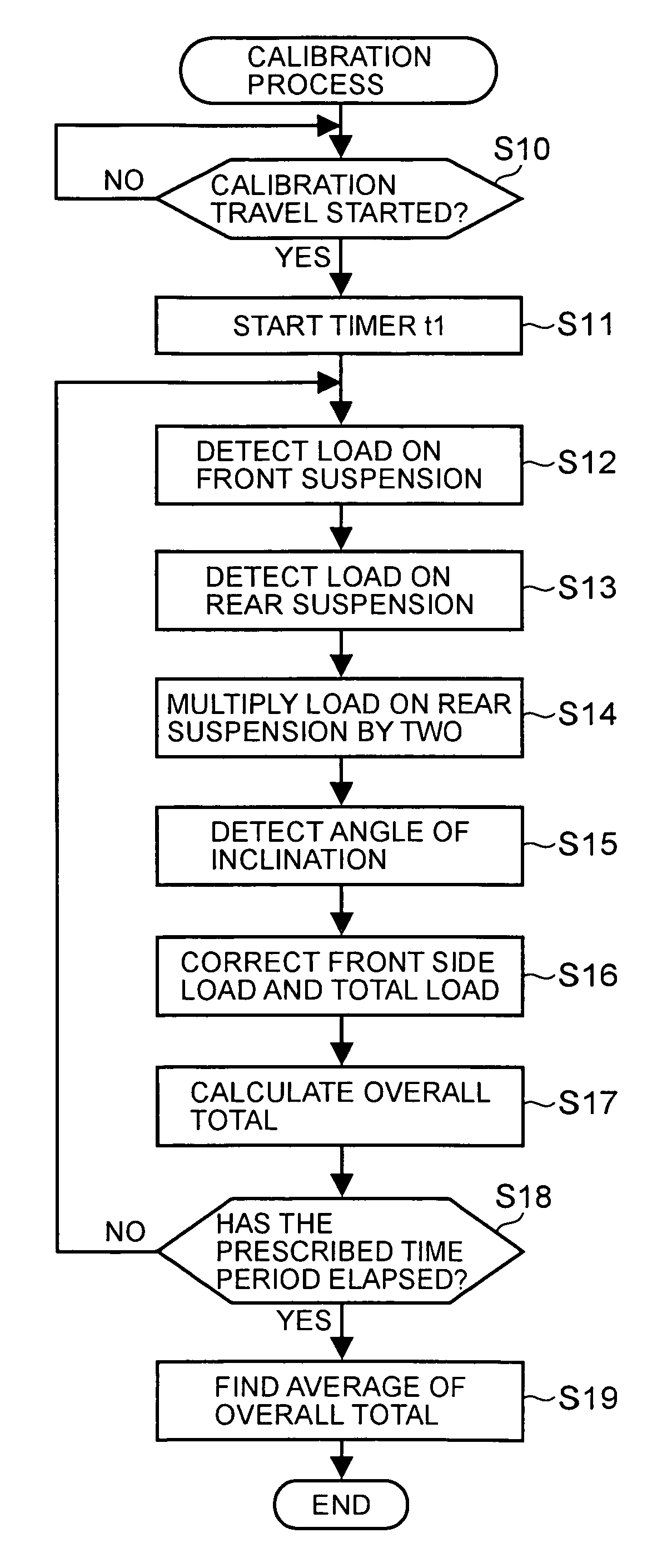
To measure loaded weight in respective work statuses of a dump truck. The loaded weight of a dump truck 11 is calculated and stored at prescribed time intervals. It is judged whether or not the dump truck 11 has transferred to a transporting status (S31-S33), and if it has transferred to a transporting status (S31: YES, S32: YES, S33: YES), then the transported weight G1 at the end of loading and immediately before transition to the transporting status is calculated and stored (S34). The transported weight G2 during the period in which the truck is in the transporting status is also calculated and stored (S35). If the truck has transferred from the transporting status to an unloading status (S36: YES), then the transported weight G3 before unloading is calculated and stored (S37). A transported weight selected from these respective transported weights G1-G3 is read out and output to a display device, or the like (S38, S39). Thereby, it is possible to measure the transported weight at a previously established plurality of measurement timings.

Description

BACKGROUND OF THE INVENTION[0001]1. Field of the Invention[0002]The present invention relates to a loaded weight measurement method and loaded weight measurement device for a dump truck.[0003]2. Description of the Related Art[0004]A method is known in the prior art (Japanese Patent Laid-open No. 61-34425) in which the weight of cargo is measured by detecting the load applied respectively to the front wheels and the rear wheels of a dump truck and correcting these detected loads on the basis of the angle of inclination of the vehicle and the center of gravity of the vehicle.[0005]According to the prior art technology described in Japanese Patent Laid-open No. 61-34425, it is possible to determine the weight of a cargo simply by detecting the loads applied respectively to the front wheels and rear wheels. However, in this prior art technology, no consideration is given to the timing at which the loaded weight is measured, and hence the measurement timing is fixed.[0006]A dump truck is...

Claims


Application Information

Patent Timeline
Patent Type & Authority Patents(United States)
IPC IPC(8): G01G19/08B60G5/00B60G17/015B60G17/017B60G17/018G01G23/00
CPCB60G5/00B60G17/015B60G17/017B60G17/018G01G23/002G01G19/08B60G2200/324B60G2400/252B60G2400/61B60G2200/318
Inventor TAKEDA, SHU
Owner KOMATSU LTD
Learn More