Inkjet printing apparatus and inkjet printing method

a printing apparatus and inkjet technology, applied in the field of inkjet printing apparatus and inkjet printing method, can solve the problems of reducing printing density, reducing lines, and reducing lines, and reducing printing density, so as to reduce printing density, reduce ink droplets, and increase the discharge amount of ink droplets

Active Publication Date: 2008-07-08
CANON KK
View PDF8 Cites 22 Cited by
  • Summary
  • Abstract
  • Description
  • Claims
  • Application Information

AI Technical Summary

Benefits of technology

[0009]However, although decreasing the ink discharge amount in the non-edge portions reduces ink bleed and provides clear edge portions of characters and reduce lines as disclosed in Japanese Patent Laid-Open Application No. 05-278221, it also decreases printing density. On the other hand, increasing the discharge amount of ink droplets to increase the printing density of characters and the like can result in more than a little ink bleed in edge portions of characters and reduce lines.
[0011]The present invention has been made in view of the above circumstances and has an object to provide an inkjet printing apparatus capable of printing characters and reduce lines with clear edge portions and high density.
[0012]The present invention provides an inkjet printing apparatus capable of printing characters and reduce lines with clear edge portions and high density. Also, by performing multiple scans for printing using a single nozzle array per printhead or two nozzle arrays per printhead for the same color, the inkjet printing apparatus can print high-density, high-quality characters and line drawings while maintaining better definition.

Problems solved by technology

However, although decreasing the ink discharge amount in the non-edge portions reduces ink bleed and provides clear edge portions of characters and reduce lines as disclosed in Japanese Patent Laid-Open Application No. 05-278221, it also decreases printing density.
On the other hand, increasing the discharge amount of ink droplets to increase the printing density of characters and the like can result in more than a little ink bleed in edge portions of characters and reduce lines.
Moreover, in an inkjet printing apparatus which applies the same color ink from multiple nozzle arrays of printheads, any misalignment among the nozzle arrays of the printheads can result in unclear edge portions of characters and reduce lines.
Furthermore, with a printing apparatus which uses multi-pass printing, variations in paper feed can cause misalignment, resulting in blurred edge portions of characters and reduce lines.

Method used


Image

  • Inkjet printing apparatus and inkjet printing method
  • Inkjet printing apparatus and inkjet printing method
  • Inkjet printing apparatus and inkjet printing method

Examples


first embodiment

[0025]Embodiments of a printing apparatus according to the present invention will be described with reference to the drawings. Incidentally, they will be described by taking as an example an inkjet printing apparatus capable of printing color images using an inkjet printing scheme.

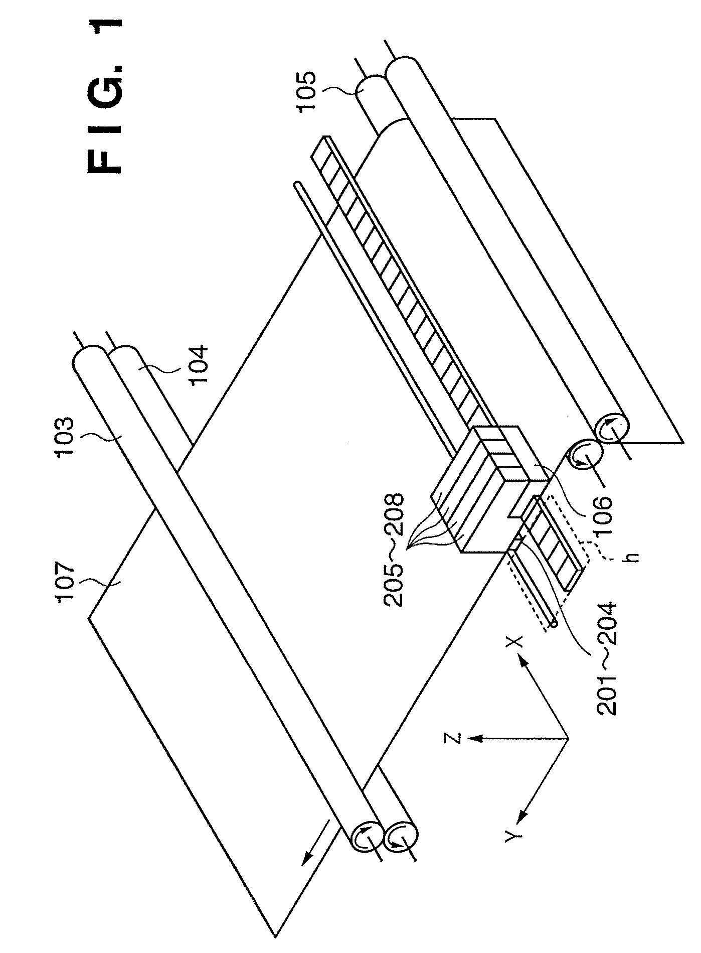
[0026]FIG. 1 is a schematic perspective view showing the configuration of an embodiment of an inkjet printing apparatus to which the present invention can be applied. In FIG. 1, reference numerals 205 to 208 denote ink cartridges. Ink cartridges 205 to 208 include ink tanks containing four color inks (black, cyan, magenta, and yellow: Bk, C, M, and Y), respectively, and four printheads 201 to 204 corresponding to the four color inks.

[0027]Reference numeral 103 denotes a paper feed / drive roller, which rotates in the direction of the arrow in the figure while holding down recording medium 107 in conjunction with an auxiliary roller 104, and thereby conveys the recording medium 107. Furthermore, the paper fee...

second embodiment

[0053]A second embodiment of the present invention makes it possible to print high-density, high-quality characters and line drawings while maintaining better definition by performing two or more scans for printing with each printhead to increase the duty factor for printing of the non-edge portion over the duty factor for printing of the edge portion.

[0054]FIG. 9 is an overall functional block diagram showing data processing according to the second embodiment. FIG. 10 is a flowchart illustrating the second embodiment. Edge data 2001 and non-edge data 2005 are generated through an edge and non-edge detecting process 2000 (Step S201).

[0055]In an odd scan for printing (Step S202), the edge data is subjected to a first edge reducing process (Step S203) by a first edge reducing mask 2002 to generate edge reduced data 2004. On the other hand, the non-edge data is subjected to a first non-edge reducing process (Step S204) by a first non-edge reducing mask 2006 to generate non-edge reduced...

third embodiment

[0058]A third embodiment of the present invention relates to a method for printing edge portions with a single nozzle array 201-1, and non-edge portions with two nozzle arrays 201-1 and 201-2 of the printhead 201 to reduce degradation of character quality due to misalignment of the printheads.

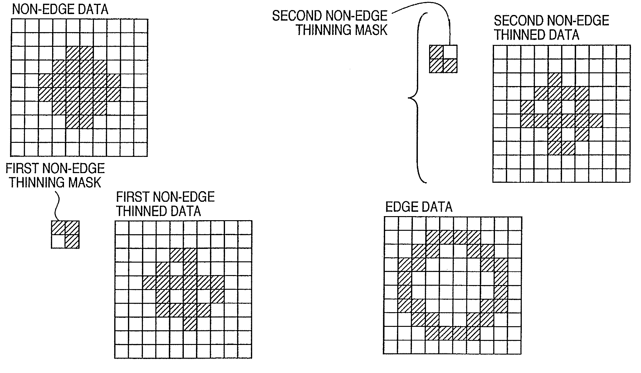
[0059]FIGS. 11A to 11H are diagrams illustrating the operation of edge and non-edge reducing processes according to the third embodiment of the present invention. The non-edge data in FIG. 11A is ORed with the first non-edge mask of a 75% duty factor to generate the first non-edge reduced data in FIG. 11B. It is assumed here that the first non-edge mask is composed of a 2×2 matrix and that the pixels in the non-edge data are ORed with it repeatedly in units of 2×2 pixels.

[0060]Similarly, the non-edge data is ORed with the second non-edge mask of a 75% duty factor to generate the second non-edge data in FIG. 11C. Dots are generated in the first non-edge data and second non-edge data which corres...


PUM


Abstract

An inkjet printing apparatus includes an edge detecting unit adapted to detect an edge portion and a non-edge portion in the image data; a memory adapted to store a plurality of edge reducing masks used to reduce image data in the edge portion and a plurality of non-edge reducing masks used to reduce image data in the non-edge portion; a reduced data generating unit adapted to generate multiple sets of edge reduced data from image data in the edge portion using the plurality of edge reducing masks and to generate multiple sets of non-edge reduced data from image data in the non-edge portion using the plurality of non-edge reducing masks; and a printing data generating unit adapted to generate multiple sets of printing data by combining the multiple sets of edge reduced data and the multiple sets of non-edge reduced data.

Description

BACKGROUND OF THE INVENTION[0001]1. Field of the Invention[0002]The present invention relates to an inkjet printing apparatus and an inkjet printing method for discharging ink from nozzle arrays of printheads for printing.[0003]2. Description of the Related Art[0004]Inkjet printing apparatuses which print on various recording media by discharging ink are capable of high-density, high-speed printing operation. Also, the inkjet printing scheme has many advantages including low running costs and low noise during printing operation. Consequently, inkjet printing apparatuses have been commercialized and used as stationary printers, portable printers, or other peripheral devices for various purposes.[0005]Known printing schemes for inkjet printing apparatuses include the so-called serial printing scheme in which a carriage which carries a printhead and ink tank scans over a recording medium, discharges ink from nozzle arrays of the printhead, and thereby prints on the scanned area. In thi...

Claims


Application Information

Patent Timeline
Patent Type & Authority Patents(United States)
IPC IPC(8): B41J2/205
CPCH04N1/4092G06K15/02
Inventor KANEMATSU, DAIGORONAGAMURA, MITSUTOSHIFURUICHI, TOMOMISUZUKI, KAZUOOGATA, TAKAO
Owner CANON KK
Why Eureka
Try Eureka