Feedthrough for electrical connectors

a technology for electrical connectors and feedthroughs, applied in the direction of contact member manufacturing, contact member assembly/disassembly, medicine/surgical connectors, etc., can solve the problems of unsatisfactory leakage rate on testing, low yield, tedious and slow, etc., to prevent the transfer of potentially dangerous materials, reduce the perimeter of the cross section, and increase the hermetic

Inactive Publication Date: 2008-07-08
COCHLEAR LIMITED
View PDF17 Cites 241 Cited by
  • Summary
  • Abstract
  • Description
  • Claims
  • Application Information

AI Technical Summary

Benefits of technology

[0014]The present invention also potentially allows more flexibility in the design of feedthrough devices by providing control over the position and configuration of the conductors through the device, the physical shape and size of the device, the number of conductors used and the overall hermeticity of the feedthrough device.
[0106]The present invention also provides the ability to create a feedthrough device having a relatively denser array of conductive structures than prior art devices, as the conductive components can be spaced closer together than is achievable in traditional devices.

Problems solved by technology

In such applications, the vacuum tubes had to be sealed because they could only operate under low-pressure conditions.
As the environment of living tissue and body fluids is relatively corrosive and devices may contain materials which may be detrimental if exposed to the patient, a hermetic feedthrough device is used to provide a barrier between the electronic components of the device and the external corrosive environment of the human body.
While useful, this method is tedious and slow and does not necessarily guarantee a hermetic seal and generally results in unsatisfactory leakage rates on testing and low yields.
A major disadvantage of this last method is that, historically the manufacturing process has been performed by hand.
Such a method of manufacture can lead to inaccuracies and be time consuming, expensive and labour intensive.
Moreover, the feedthrough devices resulting from such a process do not necessarily have precisely positioned electrical conductors, with the position of the conductors being greatly dependent upon the process itself.
The problems in fabricating such a feedthrough device on such a large scale are therefore quite significant, especially when one considers the relatively high degree of labour intensity and specialisation of current fabricating methods.
While the above described prior art feedthrough devices and fabrication methods have proven successful, it is a relatively slow and labour intensive process to manufacture such devices.
The method of manufacture of the feedthrough also presents limitations as to the construction of the feedthrough.

Method used


Image

  • Feedthrough for electrical connectors
  • Feedthrough for electrical connectors
  • Feedthrough for electrical connectors

Examples


Embodiment Construction

[0151]The steps of one embodiment of a method of forming an electrically conducting feedthrough according to the present invention are depicted in FIG. 11.

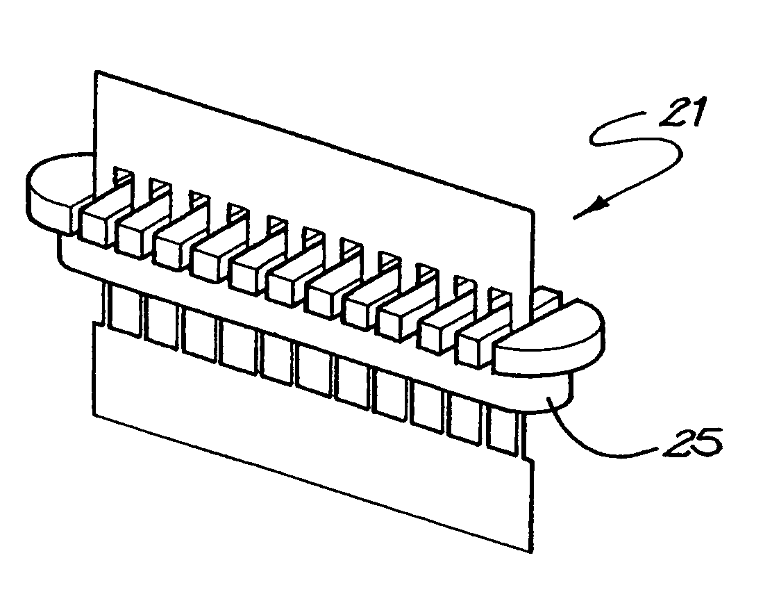
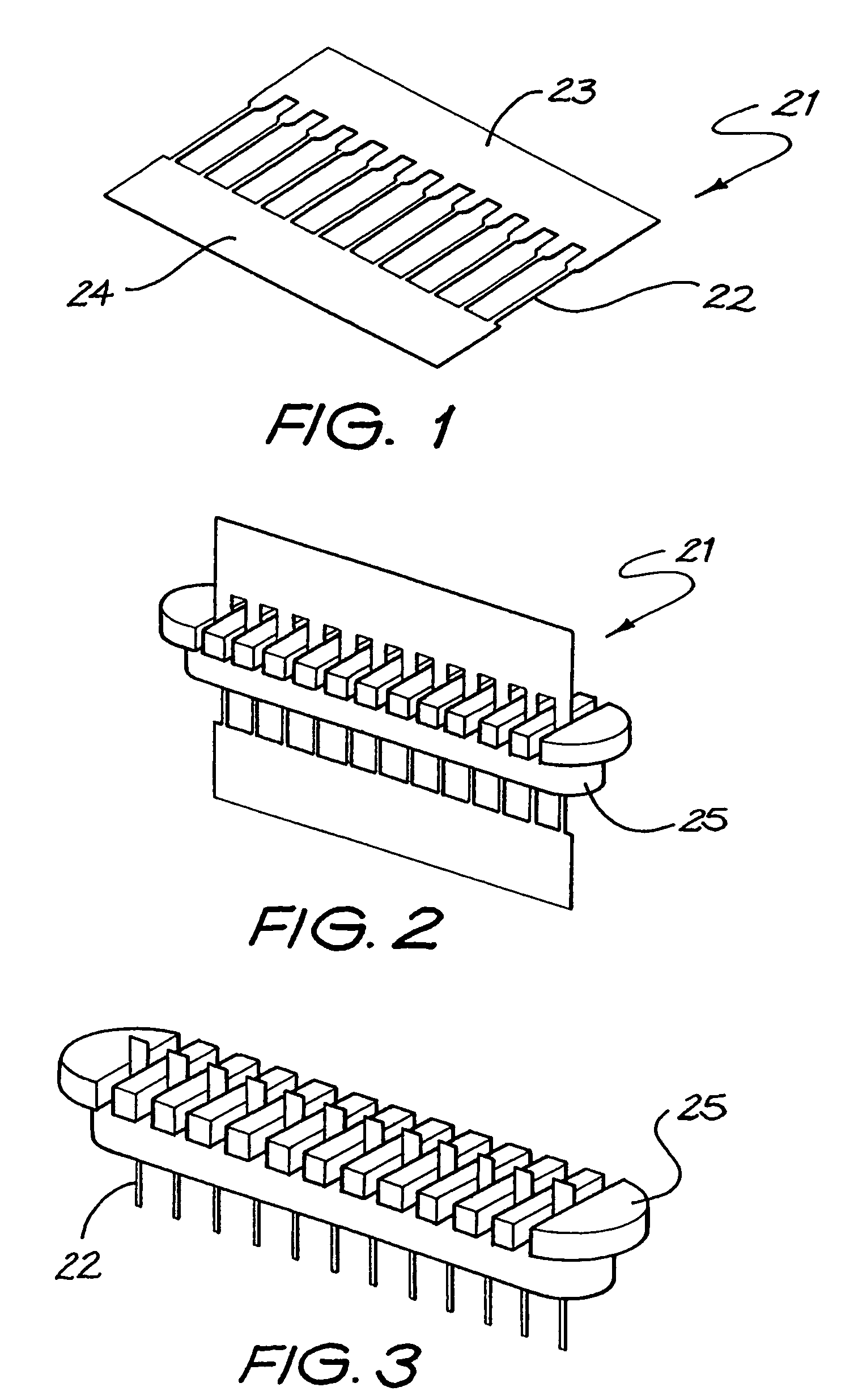
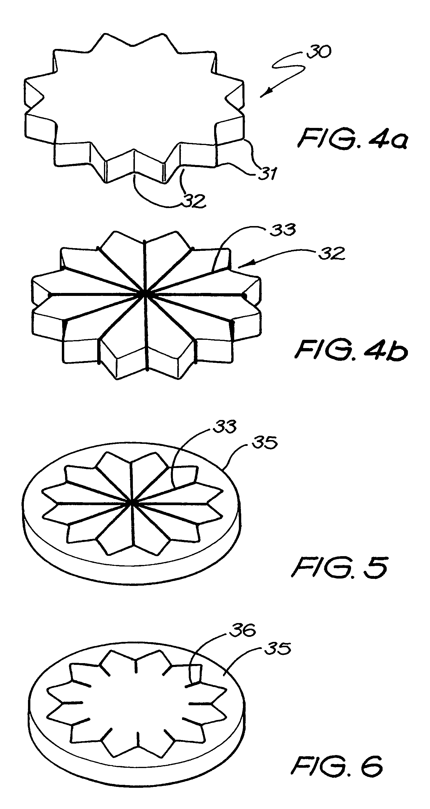
[0152]The method 10 comprises a first step 11 of forming an electrically conductive structure comprising a sacrificial component and non-sacrificial component. Different examples of such structures are depicted in FIGS. 1, 4b, 7, and 10b.

[0153]The method further comprises a step 12 of coating or moulding a non-electrically conductive insulative member on to at least a portion of the non-sacrificial component and not on to at least a portion of the sacrificial component of the conductive structure.

[0154]Still further, the method comprises a step 13 of then removing at least that portion of the sacrificial component of the conductive structure on to which the insulative member has not been coated or moulded.

[0155]Following removal of the sacrificial component of the conductive structure, the green body of the insulator can undergo ...


PUM

PropertyMeasurementUnit
diameteraaaaaaaaaa
temperatureaaaaaaaaaa

Abstract

A method (10) of forming an electrically conducting feedthrough. The method (10) comprises a first step (11) of forming an electrically conductive structure (21) comprising a sacrificial component and a non-sacrificial component. At least a portion of the non-sacrificial component can then be coated with a relatively electrically insulating material (35) prior to removal of at least a portion of the sacrificial component from the electrically conductive structure. The structure of the feedthrough provides electrical connection through the wall of a housing of an implantable component while preventing unwanted transfer of materials between the interior of the component and the surrounding environment.

Description

CROSS-REFERENCE TO RELATED APPLICATIONS[0001]This application claims the priority of and is a national stage application of PCT Application No. PCT / AU2003 / 001288, entitled, “Feedthrough for Electrical Connectors,” filed on Sep. 30, 2003, which claims the priority of Australian Patent No. 2002951734, Australian Patent No. 2002951738, Australian Patent No. 2002951739, and Australian Patent No. 2002951740 that were each filed on Sep. 30, 2002. The entire disclosure and contents of the above applications are hereby incorporated by reference.FIELD OF THE INVENTION[0002]The present invention relates to a method of forming relatively small or miniature electrical connector systems. More specifically, the present invention relates to a method of forming hermetically sealed but electrically conducting feedthroughs for devices, including biosensors and implantable devices. Electrically conducting feedthroughs are also described. Examples of implantable devices that can use such feedthroughs i...

Claims


Application Information

Patent Timeline
Patent Type & Authority Patents(United States)
IPC IPC(8): H01R13/02A61N1/05H01R13/52H01R43/00H01R43/24
CPCA61N1/05A61N1/0541H01R13/5224H01R43/24H01R2201/12Y10T29/4922Y10S439/909Y10T29/49117Y10T29/5149Y10T29/49204Y10T29/49002Y10T29/49174Y10T29/49073Y10T29/49169
Inventor DARLEY, DEREK IANMCCUSKER, DESMOND ANDREWMILOJEVIC, DUSANPARKER, JOHN
Owner COCHLEAR LIMITED
Why Eureka
Try Eureka