Spectroscopy system

a spectroscopy and monochromator technology, applied in the field of spectroscopy, can solve the problems of inelastic scattering of light and the interaction of light with the material at and near the surfa

Inactive Publication Date: 2008-07-08
WAFERMASTERS
View PDF19 Cites 5 Cited by
  • Summary
  • Abstract
  • Description
  • Claims
  • Application Information

AI Technical Summary

Problems solved by technology

However, some of the light interacts with the material at and near the surface and is scattered inelastically due to excitation of vibrational, rotational, and / or other low-frequency modes of the material.

Method used


Image

  • Spectroscopy system
  • Spectroscopy system
  • Spectroscopy system

Examples


Embodiment Construction

[0052]Systems and techniques provided herein may allow for more flexible spectroscopy than provided by existing spectroscopy systems.

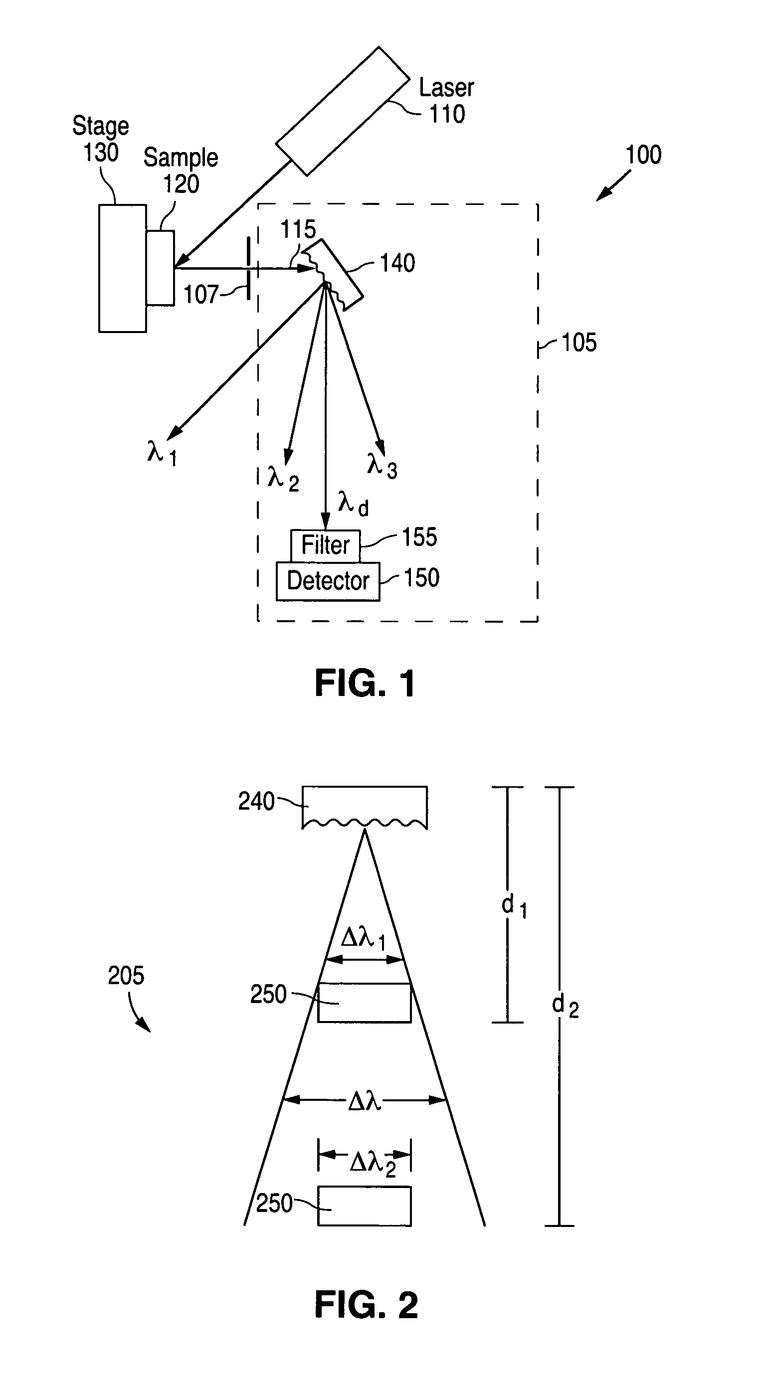
[0053]For optical spectrometers, monochromators are used to isolate particular wavelengths or wavelength ranges of interest. Typically, a user selects a particular monochromator based on the anticipated application. For example, for Raman spectroscopy applications, bulky high resolution monochromators are generally used, to obtain high resolution data for the Raman peaks of interest. For other applications, a user may wish to choose a compact and easy to use low resolution monochromator.

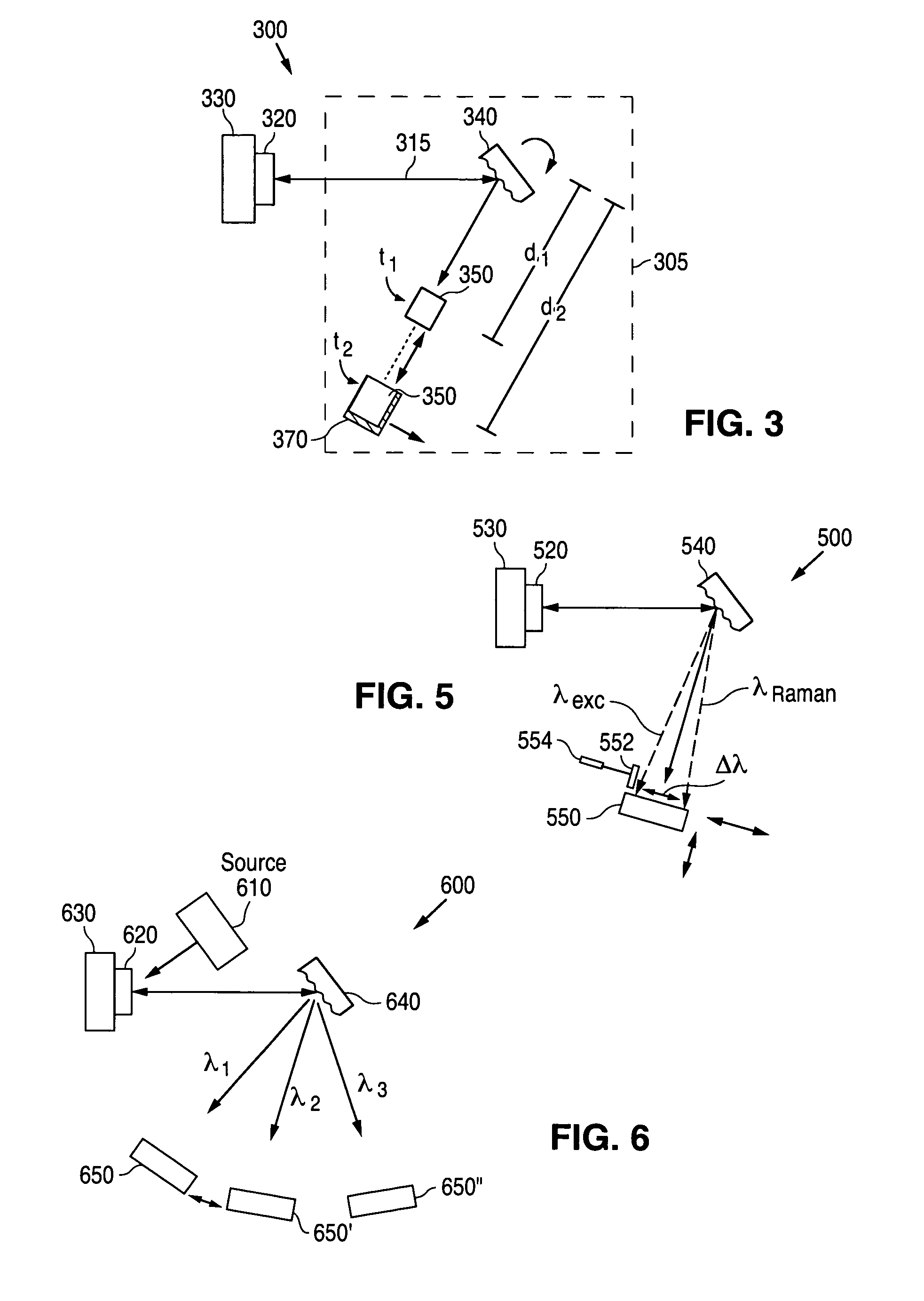
[0054]In order to provide enhanced flexibility, systems and techniques provided herein include monochromator and spectrometer designs with zoom in / zoom out capability. As a result, both low and high resolution spectroscopy may be performed.

[0055]FIG. 2 is a top view of a monochromator 205 illustrating the way in which the resolution of system 200 depends on the distance...


PUM

PropertyMeasurementUnit
Raman shiftaaaaaaaaaa
wavelengthaaaaaaaaaa

Abstract

Systems and techniques for improved spectroscopy. In some embodiments, mechanical and / or optical zoom mechanisms may be provided for monochromator systems. For example, movable detector systems allow a detector to be positioned with respect to a dispersive element in order to obtain a first resolution. The detector systems may then allow the detector to be positioned with respect to a dispersive element to obtain a second different resolution. In some embodiments, spectroscopy of a first sample region may be performed using a plurality of excitation wavelengths. Multiple detectors may be positioned to receive light associated with different ones of the plurality of excitation wavelengths.

Description

CROSS REFERENCE TO RELATED APPLICATION[0001]This application is a continuation-in-part of U.S. patent application Ser. No. 11 / 268,148 filed on Nov. 7, 2005, which is hereby incorporated by reference in its entirety.BACKGROUND[0002]1. Field of Invention[0003]This invention generally relates to spectroscopy, particularly to monochromator systems for spectroscopy (e.g., for Raman spectroscopy).[0004]2. Related Art[0005]A number of techniques may be used to obtain information about materials. One technique that may be used is Raman spectroscopy. In Raman spectroscopy, laser light is incident on a surface of a material to be analyzed. Most of the light scatters elastically from the surface (which is referred to as Rayleigh scattering). However, some of the light interacts with the material at and near the surface and is scattered inelastically due to excitation of vibrational, rotational, and / or other low-frequency modes of the material. The inelastically scattered light is shifted in wa...

Claims


Application Information

Patent Timeline
Patent Type & Authority Patents(United States)
IPC IPC(8): G01J3/36G01J3/44G01N21/63G01N21/65
CPCG01J3/02G01J3/0218G01J3/0229G01J3/0237G01J3/0262G01N21/65G01J3/10G01J3/2803G01J3/32G01J3/36G01J3/44G01J3/0291
Inventor YOO, WOO SIK
Owner WAFERMASTERS
Why Eureka
Try Eureka