
Two degree of freedom position control method, two degree of freedom position control device, and medium storage device

a position control and freedom technology, applied in the direction of adaptive control, electric controllers, instruments, etc., can solve the problems of high accuracy position control, control delay is becoming conspicuous, and output delay time is generated, so as to prevent overrun, influence of output delay, and high accuracy position control

Inactive Publication Date: 2008-07-08
KK TOSHIBA
View PDF7 Cites 0 Cited by
  • Summary
  • Abstract
  • Description
  • Claims
  • Application Information

AI Technical Summary

Benefits of technology

[0022]With the foregoing in view, it is an object of the present invention to provide a two degree of freedom position control method, two degree of freedom position control device, and medium storage device to prevent an output delay of two degree of freedom control.
[0025]It is still another object of the present invention to provide a two degree of freedom position control method, two degree of freedom position control device and medium storage device for decreasing calculation processing time, and preventing a decrease of phase margin and response deterioration.
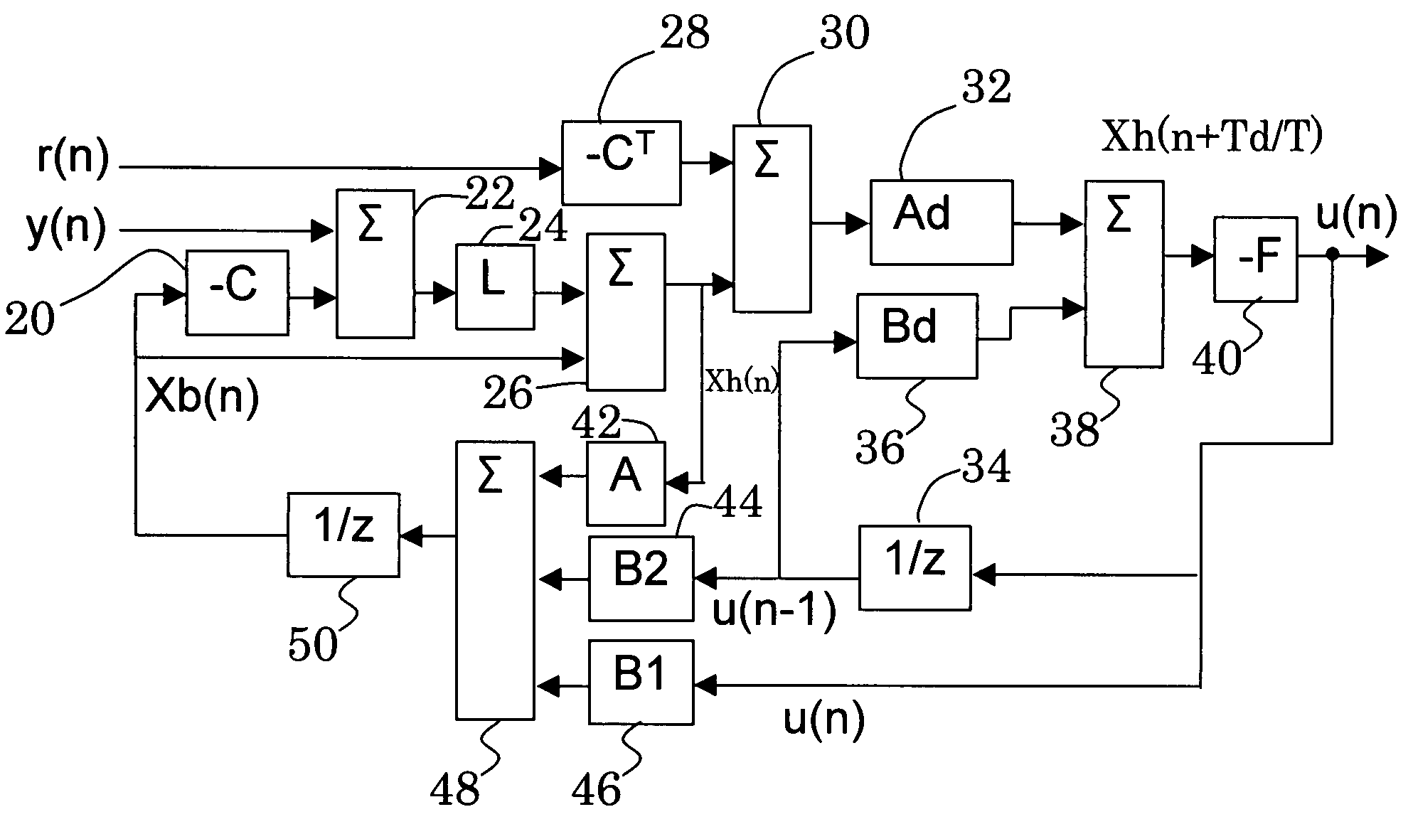
[0034]In the two degree of freedom control system for preventing overrun, the delay of output of the two degree of freedom control (computing delay and hardware delay of the drive amplifier, D / A amplifier, etc.) is considered, and the estimated state of Td, which is advanced by the amount of delay from the sample point of time, is computed, then the output is computed based on this estimated state, so even if the state changes during calculation from the sample point of time, the influence of the output delay can be prevented, and highly accurate position control can be performed, therefore an overrun can be prevented.
[0035]Also since the two degree of freedom control terms are calculated at a same sample time, the calculation sequence can be prevented from becoming complicated, and the calculation can be performed at high-speed. Also the state estimation sequence can be adhered to, so stability of the entire system can be maintained. Also the current waveform becomes smooth, which contributes to decreasing the seek time of the medium storage device and the prevention of overrun.

Problems solved by technology

However in digital control, computation processing is performed by a microcontroller, so an output delay time is generated.
Along with the recent demand for high-speed moving and high precision positioning, a control delay is becoming conspicuous in a conventional method of estimating the state once in one sample to change the drive current.
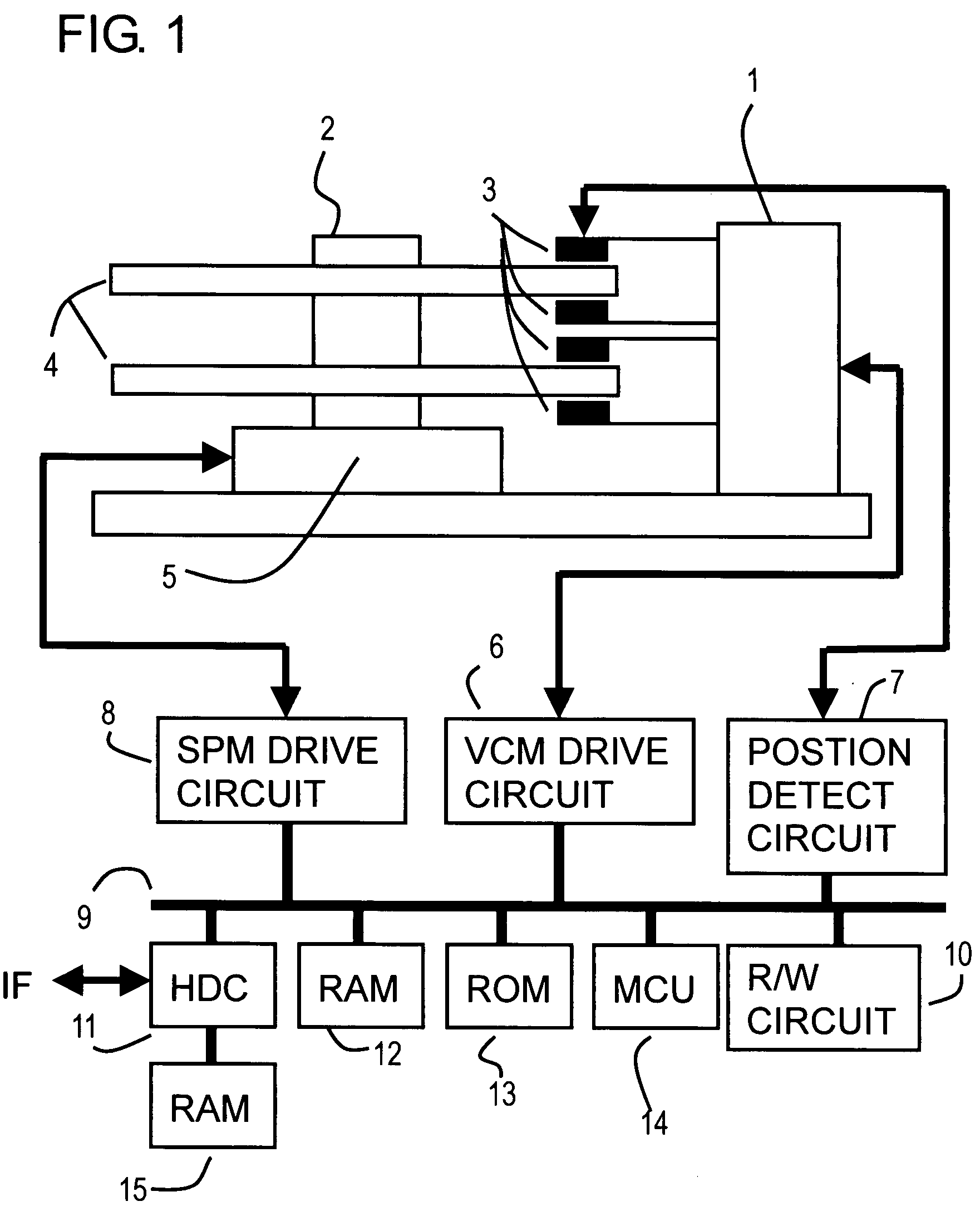
For example, in the case of the magnetic disk device, density is set to high, several tens of thousand tracks are on one disk face, and a high moving speed is demanded, so a state change becomes major during calculation even if state is estimated once and the device current is changed once in one state estimation, and an output delay makes highly accurate position control difficult, and an overrun easily occurs.

Method used


Image

  • Two degree of freedom position control method, two degree of freedom position control device, and medium storage device
  • Two degree of freedom position control method, two degree of freedom position control device, and medium storage device
  • Two degree of freedom position control method, two degree of freedom position control device, and medium storage device

Examples


first embodiment

of Two Degree of Freedom Position Control System

[0063]FIG. 5 is a block diagram depicting a first embodiment of the position control system of the present invention, and is a block diagram of the position control system for suppressing disturbance which is executed by the MCU 14 in FIG. 1. FIG. 6 is a block diagram depicting a variant form of FIG. 5, and FIG. 7 is a diagram depicting the control sequence of FIG. 5 and FIG. 6.

[0064]FIG. 5 shows a two degree of freedom position control system using a current observer which is executed by the MCU 14 in FIG. 1. First the current observer will be described. The actuator of the magnetic disk device is a rotation type. However this can be converted into and expressed as a state equation of a linear actuator shown in Expression (6). Here ‘x’ is a position (m), ‘v’ is a velocity (m / s), ‘u’ is a current (Ampere), B1 is a force constant (N / m), ‘m’ is an equivalent mass (kg), ‘u’ is an output, and ‘s’ is a Laplace operator.

[0065]s⁡(xv)=(0100)⁢(...

second embodiment

of Two Degree of Freedom Position Control System

[0113]FIG. 8 is a block diagram depicting the second embodiment of the two degree of freedom control system of the present invention, and FIG. 9 is an operation sequence diagram thereof. FIG. 8 and FIG. 9 show the configuration of a two degree of freedom control system using double multi-rate control.

[0114]Multi-rate control changes current two or three times in one sample, as shown in FIG. 8 and FIG. 9. Changing twice is called “double multi-rate configuration”, and changing three times is called “triple multi-rate configuration”.

[0115]As the double multi-rate configuration in FIG. 8 shows, a target trajectory generation section 110 generates a target trajectory r(n) in the sample(n) and a target trajectory r (n+0.5) in the sample (n+0.5) in each sample based on the target position r, and sends them to a controller 114. A position error computing section 112 computes a position error y(n) from an observed current position y (observati...

third embodiment

of Two Degree of Freedom Control System

[0149]Now an embodiment when the disturbance model is separated is shown. An example when the actuator model and disturbance model are separated in the current observer will be described. By implementing a configuration where the disturbance model is separated, a disturbance model having an arbitrary disturbance suppression characteristic can be added easily, without influencing the model of the actuator.

[0150]Therefore a current observer where a disturbance model is added can be easily constructed, and also a disturbance model having a desired disturbance characteristic can be added easily to a conventional current observer.

[0151]A calculation expression where the disturbance model is separated is created by transforming the multi-rate state estimation expressions of Expression (28) and Expression (29). In Expression (28), the states Xh(n) and Xh(n+Td / T) of Expression (28) are separated into the states Xh(n) and Xh(n+Td / T) of the actuator mode...


PUM

PropertyMeasurementUnit
timeaaaaaaaaaa
degree of freedomaaaaaaaaaa
velocityaaaaaaaaaa

Abstract

In a position control device based on a current observer control for performing two degree of freedom control, deterioration of the position accuracy caused by the output delay due to computation is prevented. In the two degree of freedom control system for preventing overrun, the delay of output of the two degree of freedom control (computing delay and hardware delay of drive amplifier, D / A converter, etc.) is considered, and the estimated state of Td which is advanced by the amount of delay from the sample point of time is computed, then output is computed based on this estimated state. So even if state changes during calculation from the sample point of time, the influence of the output delay can be prevented, and highly accurate position control can be performed, therefore overrun can be prevented.

Description

CROSS-REFERENCE TO RELATED APPLICATIONS[0001]This application is based upon and claims the benefit of priority from the prior Japanese Patent Application No. 2006-256604, filed on Sep. 22, 2006, the entire contents of which are incorporated herein by reference.BACKGROUND OF THE INVENTION[0002]1. Field of the Invention[0003]The present invention relates to a two degree of freedom position control method, two degree of freedom position control device and medium storage device using both feedback and feed forward, and more particularly to a two degree of freedom position control method, two degree of freedom position control device and medium storage device for performing two degree of freedom control using observer control.[0004]2. Description of the Related Art[0005]A device for controlling the position of an object to a target position is widely used. For example, this device is used for seek control for moving a head to a target track, which is one of the positioning controls of a ...

Claims


Application Information

Patent Timeline
Patent Type & Authority Patents(United States)
IPC IPC(8): G11B5/596
CPCG11B5/5526G05B11/01G05B13/02G11B5/596
Inventor TAKAISHI, KAZUHIKO
Owner KK TOSHIBA
Learn More