
Internal combustion engine comprising a mechanical charger and a turbo-compound

a technology of internal combustion engine and turbocompound, which is applied in the direction of steam engine plants, machines/engines, mechanical equipment, etc., can solve the problems of disadvantages of mechanical chargers, which need to be provided by internal combustion engines, and achieve rapid heating of catalytic converters, optimum efficiency ranges, and high efficiency.

Inactive Publication Date: 2008-07-15
DAIMLER AG
View PDF22 Cites 26 Cited by
  • Summary
  • Abstract
  • Description
  • Claims
  • Application Information

AI Technical Summary

Benefits of technology

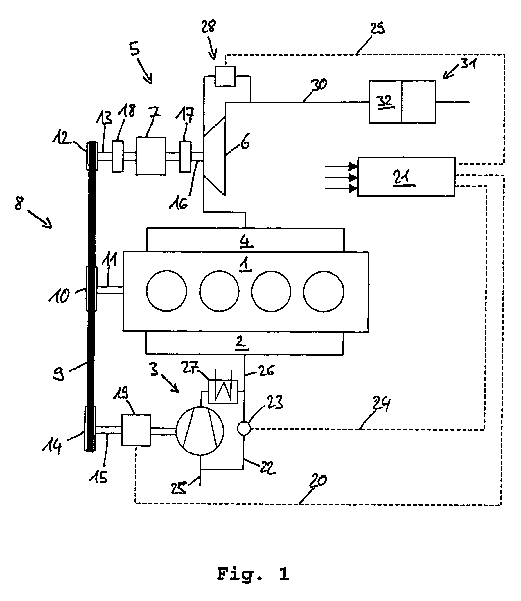
[0013]The coupling of the mechanical charger and of the turbo-compound to the internal combustion engine by means of a belt drive is particularly advantageous because a belt drive has a simple construction, can easily be mounted and requires no lubrication and scarcely any maintenance. Moreover, a belt drive allows more degrees of freedom as regards the arrangement of the components, since even relatively large center distances and multiple drives can be implemented simply and cost-effectively. Finally, low-noise operation and insensitivity to brief overloading are also advantages.
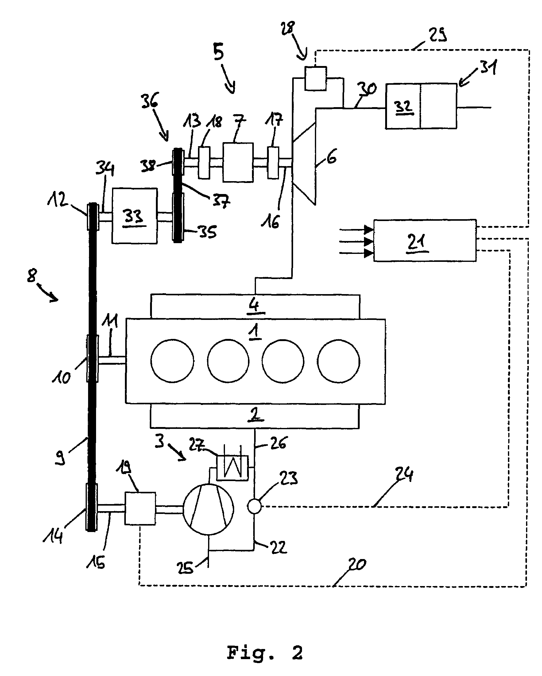
[0023]In another embodiment of the invention, the generator and the turbo-compound are coupled to one another via a second belt drive. The internal combustion engine drives the mechanical charger and the generator via the belt drive. The generator possesses a shaft, a belt pulley being provided at each of the ends of the shaft. A belt pulley is part of the belt drive of the internal combustion engine. The second belt pulley is part of the second belt drive which comprises a belt and a belt pulley of the turbo-compound. Advantageously, by the generator being interposed, it is possible to obtain further degrees of freedom with regard to the construction space. Moreover, owing to different diameters of the belt pulleys of the generator, a reduction in the rotational speed of the turbo-compound to the internal combustion engine can take place. It is thereby possible to provide the reduction gear with a lower reduction ratio.

Problems solved by technology

The power consumed by the mechanical charger, which needs to be provided by the internal combustion engine, is a disadvantage however.

Method used


Image

  • Internal combustion engine comprising a mechanical charger and a turbo-compound
  • Internal combustion engine comprising a mechanical charger and a turbo-compound
  • Internal combustion engine comprising a mechanical charger and a turbo-compound

Examples


Embodiment Construction

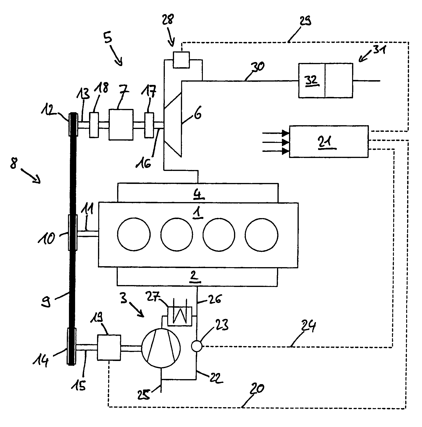
[0027]FIG. 1 illustrates a first version of the internal combustion engine 1 according to the invention. The internal combustion engine 1 is preferably a spark ignition engine for passenger cars. However, use for diesel engines, in particular for commercial vehicles, may also be envisaged. The internal combustion engine 1 has an inlet tract 2 and, assigned to this, a mechanical charger 3 and an outlet tract 4 and, assigned to this, a turbo-compound 5. The turbo-compound 5 has an exhaust gas turbine 6 and a reduction gear 7 coupled to the exhaust gas turbine 6. The internal combustion engine 1, the mechanical charger 3 and the turbo-compound 5 are coupled to one another by means of a belt drive 8. The belt drive 8 includes a belt 9, with a belt pulley 10 on a crankshaft 11 of the internal combustion engine 1, a belt pulley 12 on an output shaft 13 of the reduction gear 7 and a belt wheel 14 on a drive shaft 15 of the mechanical charger 3.

[0028]The exhaust gas turbine 6 is coupled to ...


PUM


Abstract

In an internal combustion engine comprising a mechanical charger in the form of a positive displacement compressor connected to the engine intake duct for supplying compressed air to the engine and a turbo-compound including an exhaust gas turbine connected to the engine exhaust duct for converting energy remaining in the exhaust gas to power, the exhaust gas turbine being connected to the engine via a reduction gear drive, the mechanical charger and the turbo-compound are coupled to the engine by a common belt drive including a first belt pulley mounted on the crankshaft of the engine, a second belt pulley mounted on the shaft of the reduction gear drive, and a third belt pulley mounted on the shaft of the mechanical charger.

Description

[0001]This is a Continuation-In-Part Application of International Application PCT / EP2004 / 012404 filed Mar. 11, 2004 and claiming the priority of German Application 103 55 563.3 filed Nov. 28, 2003.BACKGROUND OF THE INVENTION[0002]The invention relates to an internal combustion engine comprising a mechanical charger and an exhaust gas turbine coupled to the engine for transmitting power thereto.[0003]Internal combustion engines comprising a mechanical charger and a turbo-compound consisting of an exhaust gas turbine and a reduction gear have been known in the prior art for a long time. The mechanical charger is coupled to the internal combustion engine and compresses the air required for combustion. The turbo-compound utilizes the energy contained in the exhaust gas of the internal combustion engine by means of the exhaust gas turbine and transmits the power obtained from the exhaust gas to the internal combustion engine via a reduction gear.[0004]Particularly positive displacement m...

Claims


Application Information

Patent Timeline
Patent Type & Authority Patents(United States)
IPC IPC(8): F02G3/00F02B33/00F02B37/00F02B37/10F02G5/04F02B33/36F02B37/16F02B37/18F02B39/04F02B39/08F02B39/12F02B41/10F02B67/06
CPCF02B33/36F02B37/005F02B37/105F02B39/08F02B39/12F02B41/10F02B67/06F02B39/04F02B37/16F02B37/18Y02T10/163Y02T10/144Y02T10/12
Inventor BOTTCHER, MICHAELENDERLE, CHRISTIANHUFENDIEK, JOCHENWUNDERLICH, KLAUS
Owner DAIMLER AG
Learn More