
Vehicle suspension system incorporating swivel link assembly

a technology of swivel link and suspension system, which is applied in the direction of suspension, coupling, transportation and packaging, etc., can solve the problems of “binding” of the suspension, general limited adjustment, and increased wear at the joint, so as to improve the lateral control of the rear axle during vehicle cornering.

Active Publication Date: 2008-07-15
HOLLEY PERFORMANCE PRODUCTS
View PDF9 Cites 9 Cited by
  • Summary
  • Abstract
  • Description
  • Claims
  • Application Information

AI Technical Summary

Benefits of technology

[0006]It is another object of the invention to provide a vehicle suspension system which provides improved ride and handling.
[0009]It is another object of the invention to provide a vehicle suspension system which incorporates long lower control arms for improved pinion angle control.
[0010]It is another object of the invention to provide a vehicle suspension system which has improved anti-squat geometry.
[0011]It is another object of the invention to provide a vehicle suspension system which includes a long track bar for improved rear axle lateral control during hard cornering.
[0033]According to another preferred embodiment of the invention, the adjustable suspension member is a track bar or anti-sway bar designed for improving rear axle lateral control during vehicle cornering.
[0034]In another embodiment, the invention is an improved vehicle suspension system adapted for supporting a frame of vehicle. The suspension system includes an axle, at least one spring operatively connected to the axle and adapted for absorbing kinetic energy transferred to the frame when the vehicle is in motion, and at least one dampening device for dampening the kinetic energy absorbed by the spring. The improvement comprises an adjustable suspension member as described herein. The suspension member interconnects first and second components of the vehicle, and enables movement of the first component relative to the second component when the vehicle is in motion.

Problems solved by technology

However, due to the construction of the Heim joint, this adjustability is generally limited to a range of 45 degrees or less.
The restricted swivel adjustment promotes increased wear at the joint, increased noise, and “binding” of the suspension.

Method used


Image

  • Vehicle suspension system incorporating swivel link assembly
  • Vehicle suspension system incorporating swivel link assembly
  • Vehicle suspension system incorporating swivel link assembly

Examples


Embodiment Construction

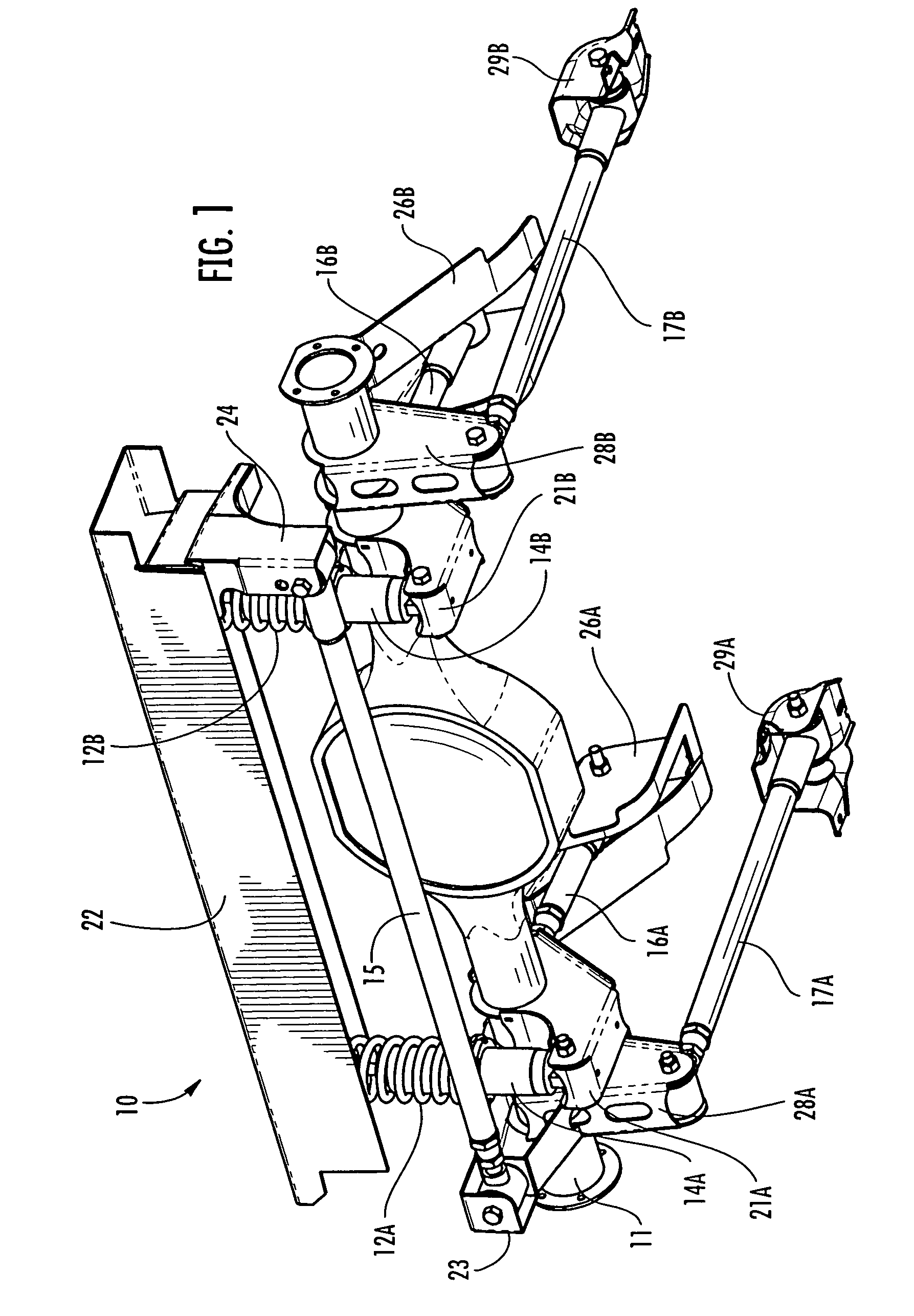
[0044]Referring now specifically to the drawings, a multi-link vehicle suspension system according to one embodiment of the present invention is illustrated in FIG. 1, and shown generally at reference numeral 10. The suspension system 10 supports the frame of the vehicle, and serves to maintain correct vehicle ride height, reduce the effect of shock forces, maintain correct wheel alignment, keep the tires in contact with the road, and control the vehicle's direction of travel.

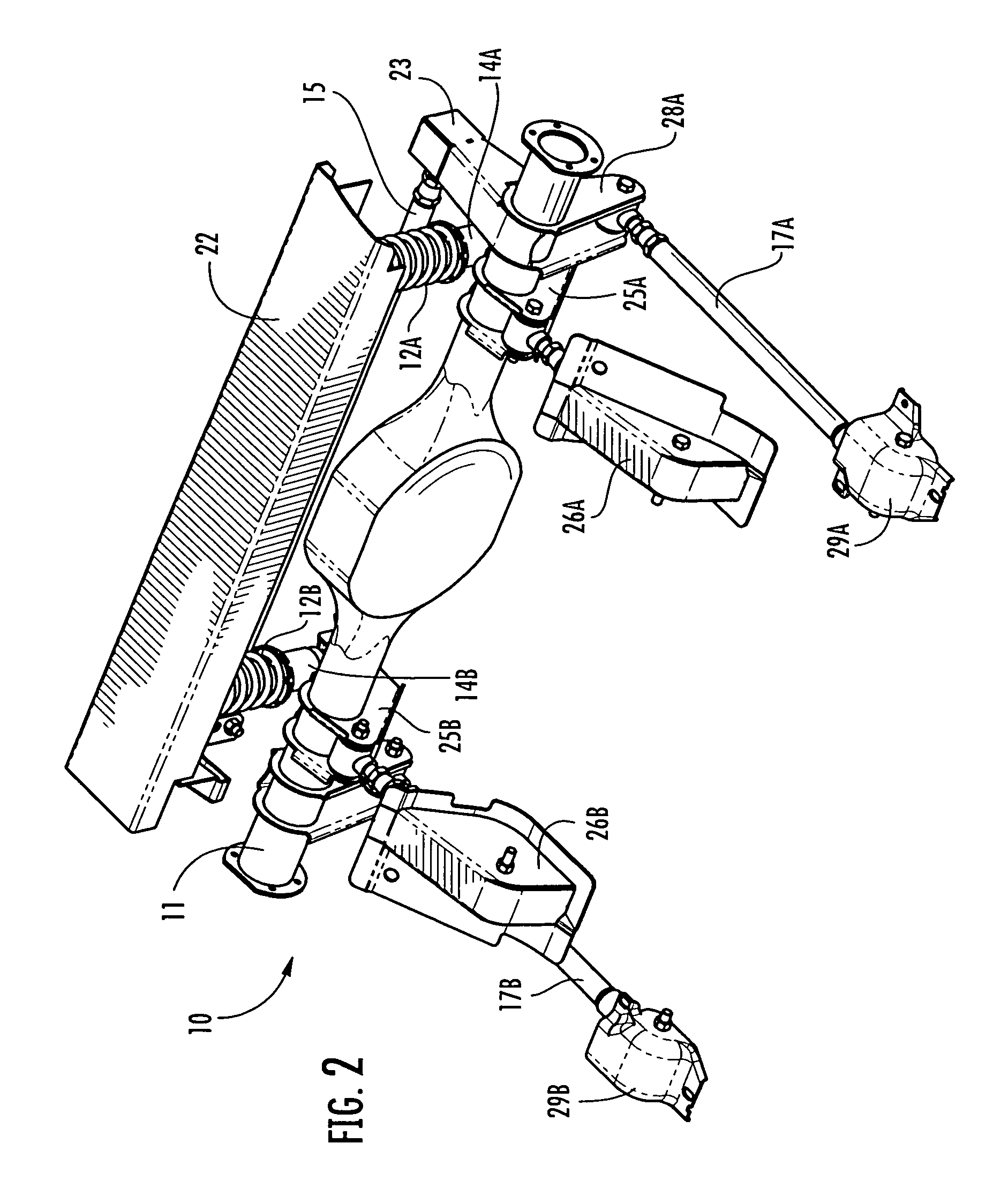
[0045]As shown in FIGS. 1-4, in one embodiment the suspension system 10 comprises standard components including a wheel axle 11, cooperating pairs of coil springs 12A, 12B and shock absorbers 14A, 14B, a lateral track bar 15, and upper and lower control arms 16A, 16B and 17A, 17B. The coil springs 12A, 12B and shock absorbers 14A, 14B (“coil-over shock absorbers”) are attached to respective axle mount brackets 21A, 21B and an upper shock cross-member 22. The coil springs 12A, 12B operate to absorb kinetic energ...


PUM


Abstract

An adjustable suspension member of a vehicle suspension system is adapted for supporting a frame of vehicle. The suspension member interconnects first and second components of the vehicle, and enables movement of the first component relative to the second component when the vehicle is in motion. The suspension member includes an elongated swivel link assembly having first and second opposite ends. The first end is operatively connected to the first component of the vehicle, and the second end is operatively connected to the second component of the vehicle. The link assembly swivels about a longitudinal axis defined by the suspension member. The swivel range is greater than 45 degrees.

Description

TECHNICAL FIELD AND BACKGROUND OF THE INVENTION [0001]This invention relates generally to a vehicle suspension system and swivel link assembly. The swivel link assembly is incorporated in one or more elongated members of the suspension system. The suspension members are allowed to fully articulate during suspension travel, thus providing smooth solid motion with no binding, and improved ride and handling.[0002]When a vehicle is in motion, the suspension system is in a dynamic state of balance, continuously compensating and adjusting for changing driving conditions. Today's suspension system is engineered to perform many functions including maintaining correct vehicle ride height, reducing the effect of shock forces, maintaining correct wheel alignment, supporting the vehicle weight, keeping the tires in contact with the road, and control the vehicle's direction of travel. The interconnection and adjustability of various suspension members, such as the upper and lower control arms, i...

Claims


Application Information

Patent Timeline
Patent Type & Authority Patents(United States)
IPC IPC(8): B60G9/00
CPCB60G7/003B60G9/00B60G21/05B60G2200/314Y10T403/32975B60G2206/82Y10T403/32213Y10T403/32983B60G2206/11
Inventor TUCKER, KYLE G.
Owner HOLLEY PERFORMANCE PRODUCTS
Learn More