
LCD back light module structure

a back light module and module technology, applied in the direction of lighting and heating apparatus, instruments, lighting support devices, etc., can solve the problems of short life of ccfl, affecting the lifespan of lcd, and the inability to increase the output of a lcd back light source as large as possible only relying on ccfl, so as to achieve the effect of prolonging the structure's lifespan

Inactive Publication Date: 2008-07-15
CHAN TSUNG WEN
View PDF2 Cites 2 Cited by
  • Summary
  • Abstract
  • Description
  • Claims
  • Application Information

AI Technical Summary

Benefits of technology

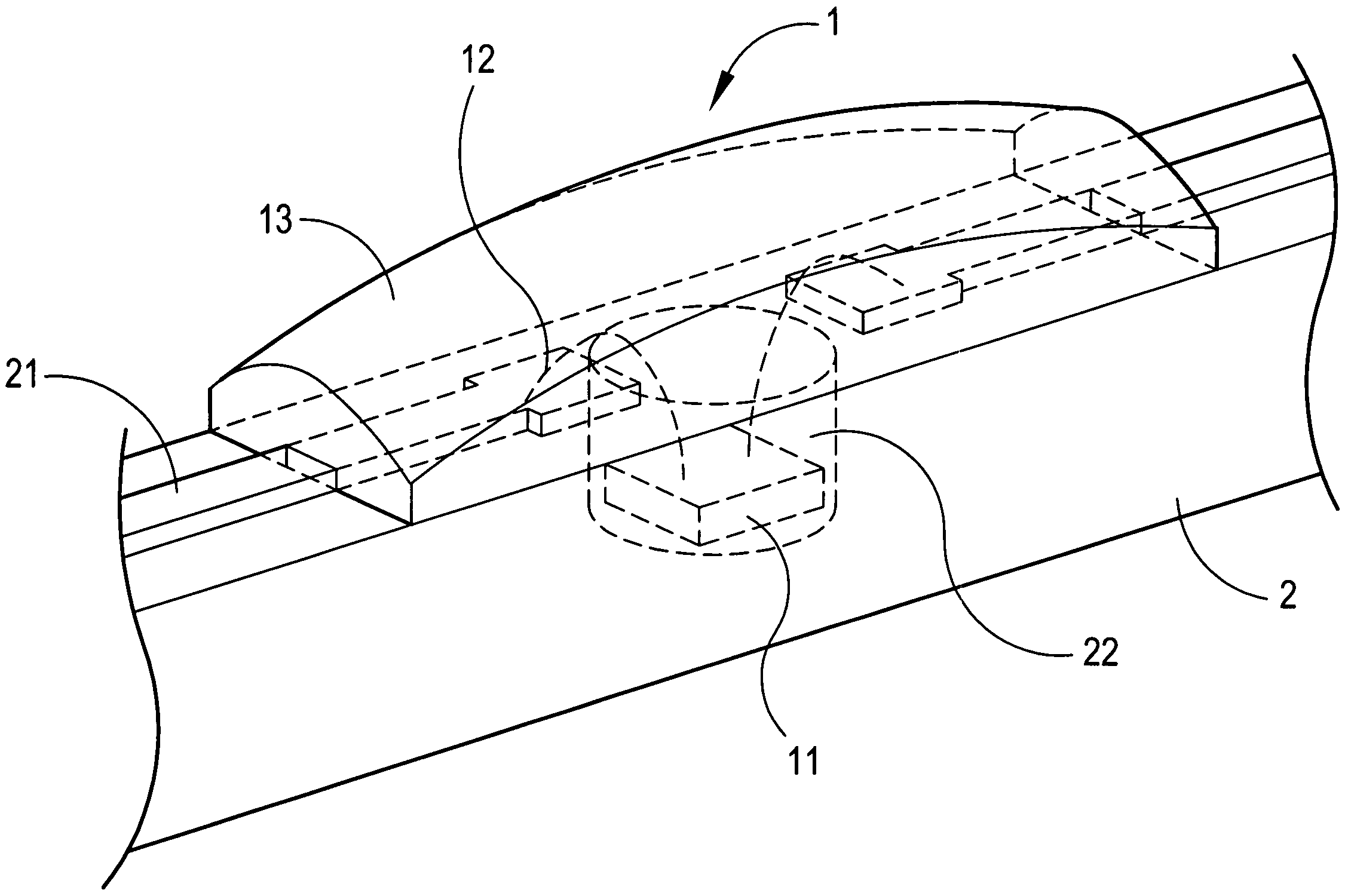
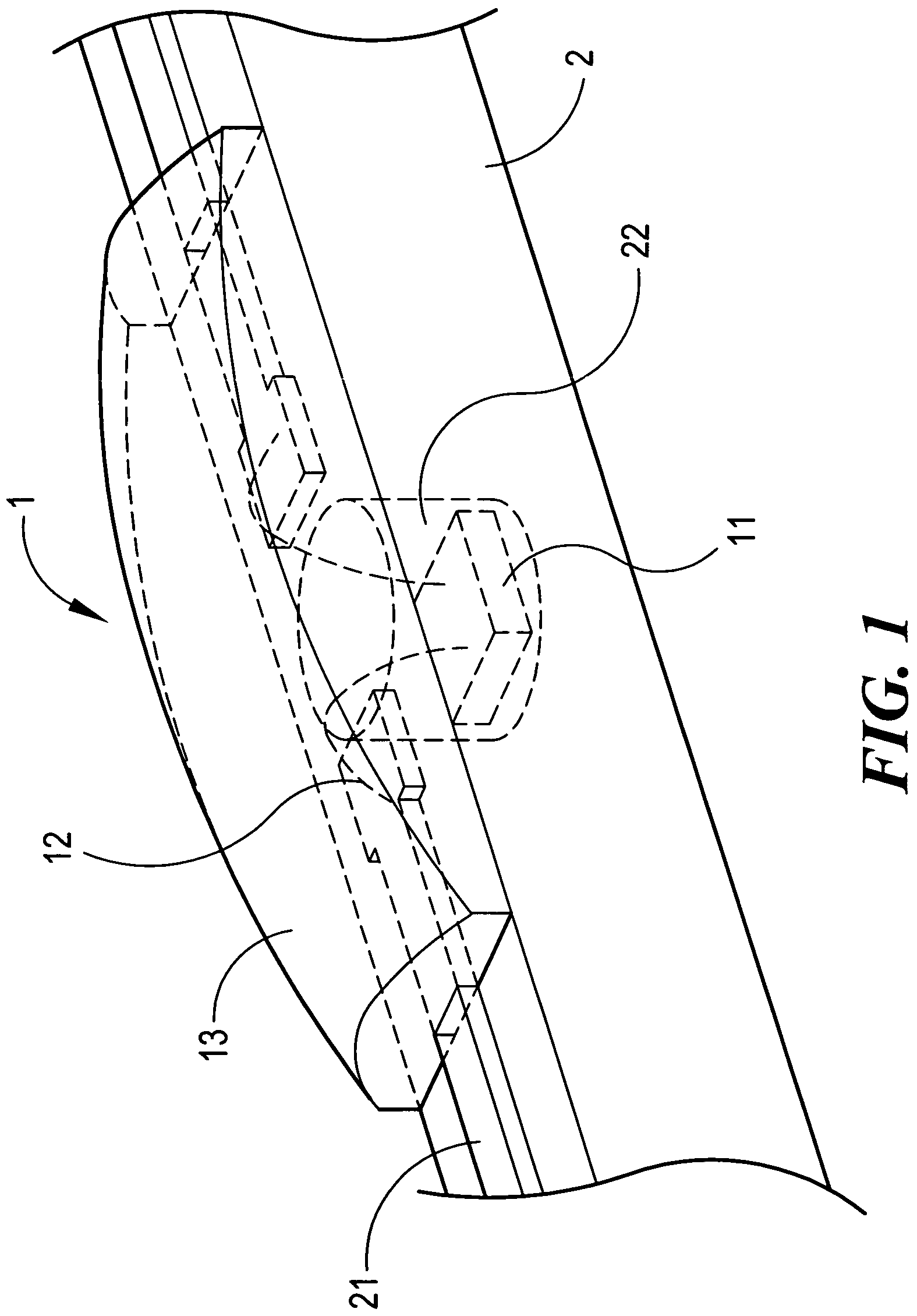
"The present invention provides a LCD back light module structure that uses a high crowned LED lens to ensure uniform light output from the LED to illuminate the LCD. The structure also employs an intensive white LED as a light source to display a highly qualified picture with a brilliant light and prolong the lifespan of the structure. The LED array is connected to a driving circuit through conductor blades on a guide stick, and the light spot of the LED die is affixed to the blind hole and the electric connection is made from the light spot to the adjacent conductor blades. The epoxy resin is infused around the blind hole to form a transparent lens for the LED, which has a high crowned configuration to ensure uniform light output from each LED. This results in numerous uniform bright spots on the LCD surface, making it appear comfortably brilliant."

Problems solved by technology

But the things always have a limit, it is impossible to increase the output of a LCD back light source as large as possible only relying on CCFL.
Moreover, the short life of CCFL affects the lifespan of the LCD.
In addition to its high power consumption, the harmful ingredient of CCFL is a killer to environmental protection.
However, it is said that the optimistic gain is very little in comparison to a substantially large power consumption and material investment.

Method used


Image

  • LCD back light module structure
  • LCD back light module structure
  • LCD back light module structure

Examples


Embodiment Construction

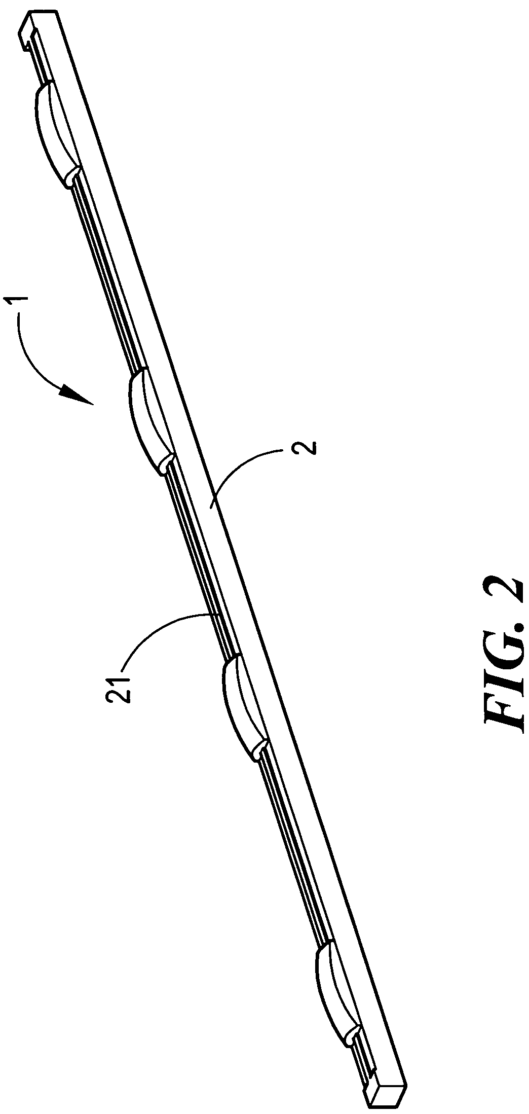
[0015]Referring to FIG. 1 through FIG. 4, the present invention comprises a guide stick 2 on which a plurality of LEDS 1 are arrayed to illuminate a LCD (not shown) with their light output, the light of different LEDS 1 can be partly over lapped to ensure a perfect distribution of light on the LCD. The guide stick 2 is equipped with a number of conductor blades 21 which being for connecting with a driving circuit (not shown) to actuate the LEDS to output light. A blind hole 22 is formed on the guide stick 2 and the light spot 11 of each LED die is affixed to its blind hole 22. The conductor wires 12 of the light spot 11 are extended to the proximate conductor blades 21 at both sides. After the necessary electric connection for each LED die is completed, the epoxy resin is infused around the blind hole 22 to form a transparent lens 13 for the LED 1. With this structure the light output from the light spot 11 is at first concentrated in the blind hole 22, and then illuminates the LCD ...


PUM


Abstract

Disclosed is a LCD back light module structure comprising one or more than one LED arrayed along an electric conducting stick which being equipped with conductor blades on its surface. The conductor blade is used for connecting the conducting stick to a driving circuit. A blind hole is formed on the conducting stick and the light spot of the Led die is buried in the blind hold and the electric connection is extended from the light spot to the adjacent two conductor blades. After being completed connection for each LED die, the epoxy resin is infused around the blind hole to form a transparent lens. The high crowned configuration of the lens enables the LED to uniformly emit the light therefrom therefore each LED forms a uniformly brilliant lighting surface on the LCD back light module structure.

Description

BACKGROUND OF THE INVENTION[0001]1. Field of the Invention[0002]He present invention relates to a LCD back light module structure, and more particularly, to a LCD back light module structure wherein a LED with high-crowned configuration is employed as a back light source to emit light uniformly on the LCD such that the LCD appears to be comfortably brilliant.[0003]2. Description of the Prior Art[0004]Generally, the white cold cathode fluorescent lamp (CCFL) is the most well-known LCD back light source. The LCD illuminated by a CCFL placed behind the LCD as a back light source. The capacity of CCFL and its driving circuit increases as the size of LCD increase. In order to strengthen the power output of the LCD back light, it is required to connect a plurality of CCFLS in series or parallel. But the things always have a limit, it is impossible to increase the output of a LCD back light source as large as possible only relying on CCFL. Moreover, the short life of CCFL affects the lifes...

Claims


Application Information

Patent Timeline
Patent Type & Authority Patents(United States)
IPC IPC(8): F21V7/04F21V21/00
CPCG02F1/133603G02F1/133606G02F2001/133607G02F1/133607
Inventor CHAN
Owner CHAN TSUNG WEN
Learn More