
Apparatus and method for three-dimensional contouring

a three-dimensional contouring and apparatus technology, applied in the field of apparatus and method for three-dimensional contouring, can solve the problems of increasing the time and expense required to establish a contoured surface, laborious process for creating physical forms, and limited use of screeding machines to smooth uncured concrete, etc., to achieve the effect of simple and effectiv

Inactive Publication Date: 2008-07-15
SOMERO ENTERPRISES INC
View PDF64 Cites 28 Cited by
  • Summary
  • Abstract
  • Description
  • Claims
  • Application Information

AI Technical Summary

Benefits of technology

The present invention is an improved device and method for contouring surfaces with poured, uncured concrete or other materials. The invention allows for the contouring of three-dimensional curved surfaces without the need for preset physical forms on both sides of the surface. The invention includes a control system that adjusts the height of the contouring machine based on the position of a target or reference point, which is tracked by a tracking device. The invention also includes a screed for spreadable materials and a target for accurate positioning. The invention provides a simple and effective way to contour surfaces to a desired shape.

Problems solved by technology

In the past, the screeding or smoothing of uncured concrete by screeding machines has been primarily limited to flat, one or two dimensional surfaces.
The creation of the physical forms is a labor intensive process that increases the time and expense necessary to establish a contoured surface.
The preset physical forms also typically only approximate the desired shape of the surface to be contoured, thereby decreasing the quality of the contoured surface.
For example, if the physical form consists of a wire, it is virtually impossible to accurately define a desired curvature.
These and other disadvantages of prior screeding techniques have led to the desire to reduce reliance on preset physical forms.
These devices have also been limited to earth grading, asphalt laying, or other non-concrete leveling tasks.
The contact nature of the sensor may introduce errors into the profile creation that are undesirable.
Such machines can only be effectively used after the subbase has been contoured to the desired shape.
This increases the amount of work required to screed a concrete surface.
This profile generation step may result in additional inaccuracies due to alignment errors of the contact sensor during the contouring step when compared with the profiling step.
This further increases the inaccuracies in the system.
Another disadvantage of the prior art is the required use of multiple sensors to determine the position of the contouring structure in three dimensions.
The use of multiple sensors increases the complexity and associated cost of the grading system, and is therefore undesirable for many applications.

Method used


Image

  • Apparatus and method for three-dimensional contouring
  • Apparatus and method for three-dimensional contouring
  • Apparatus and method for three-dimensional contouring

Examples


Embodiment Construction

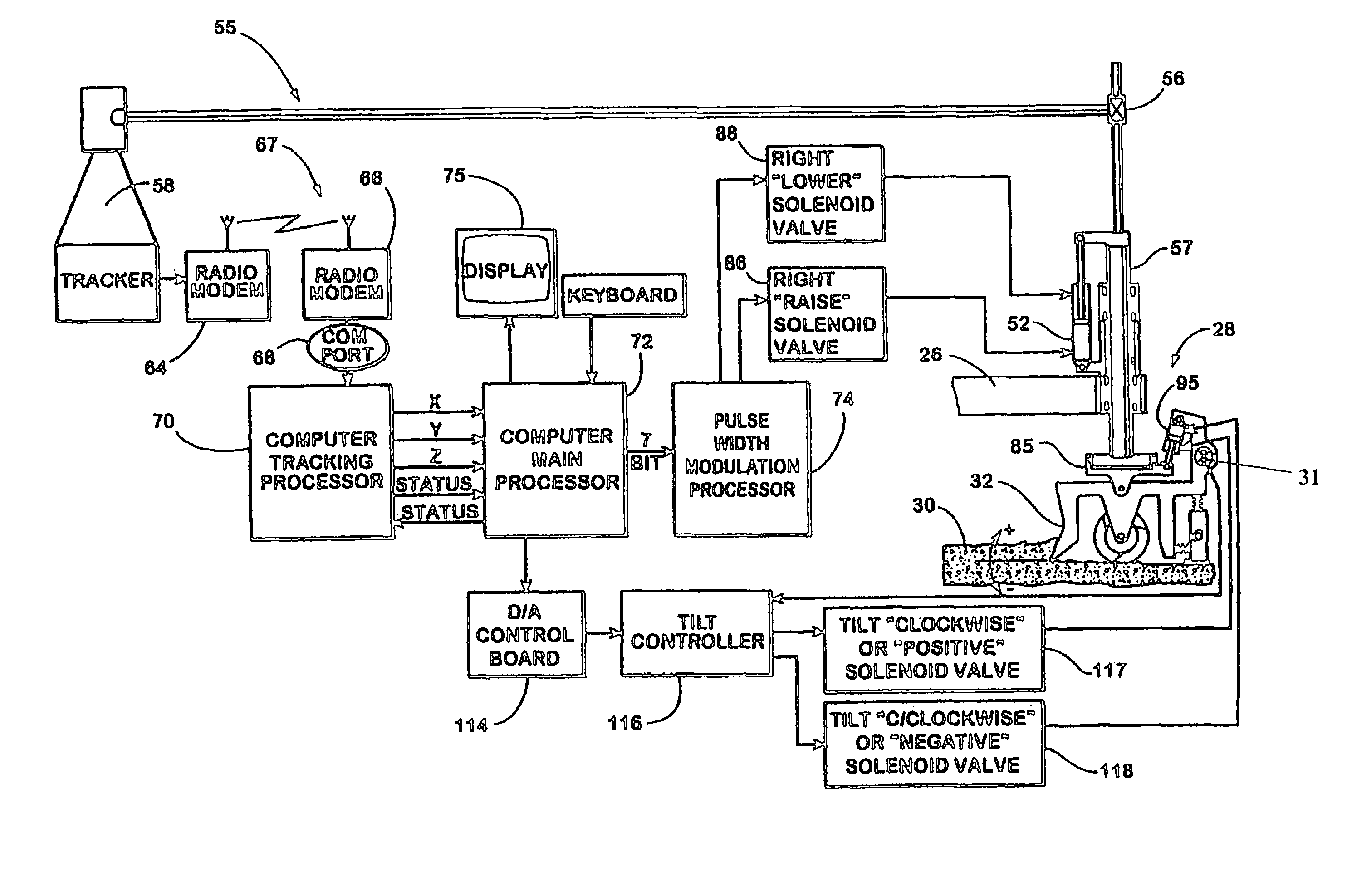
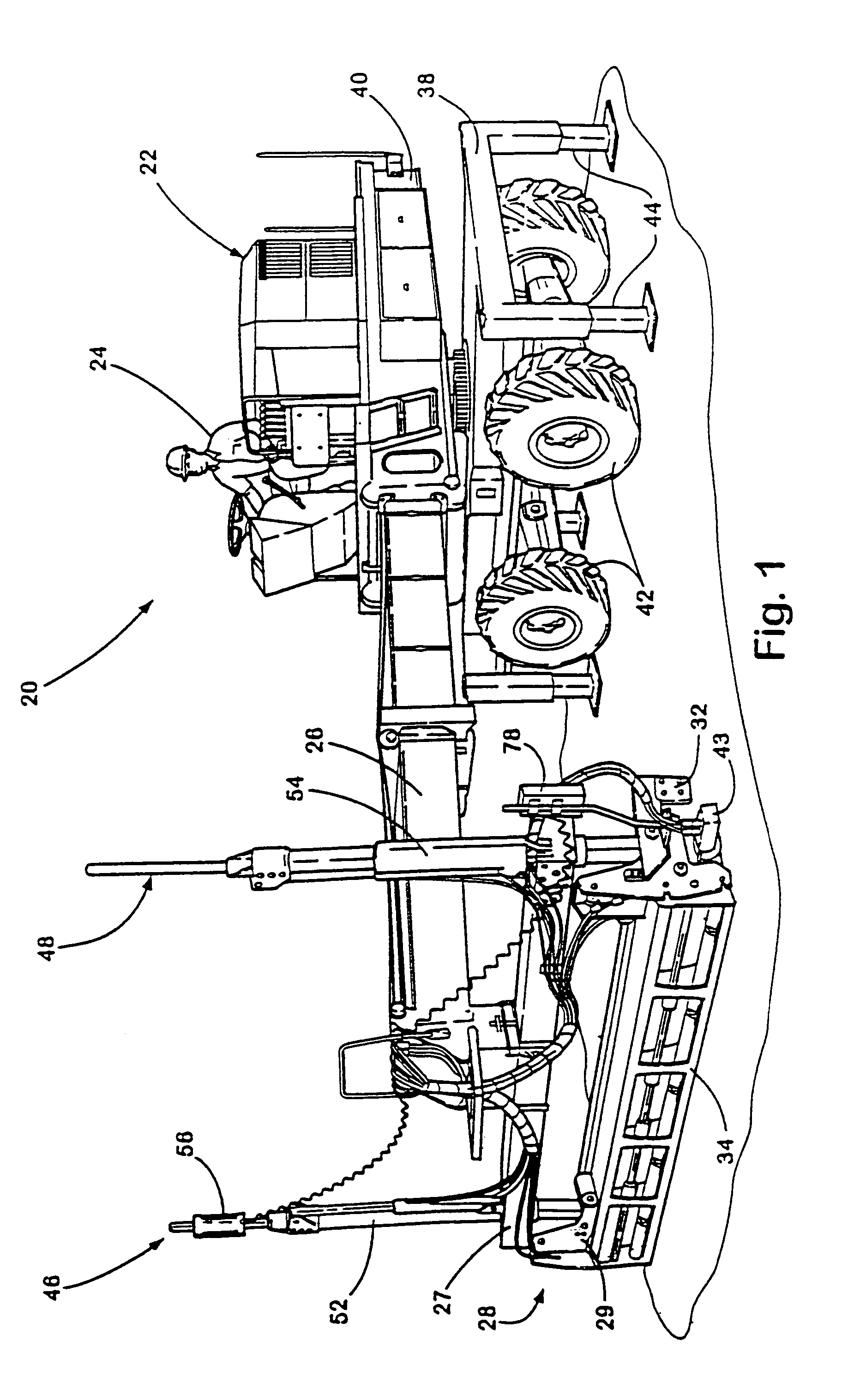
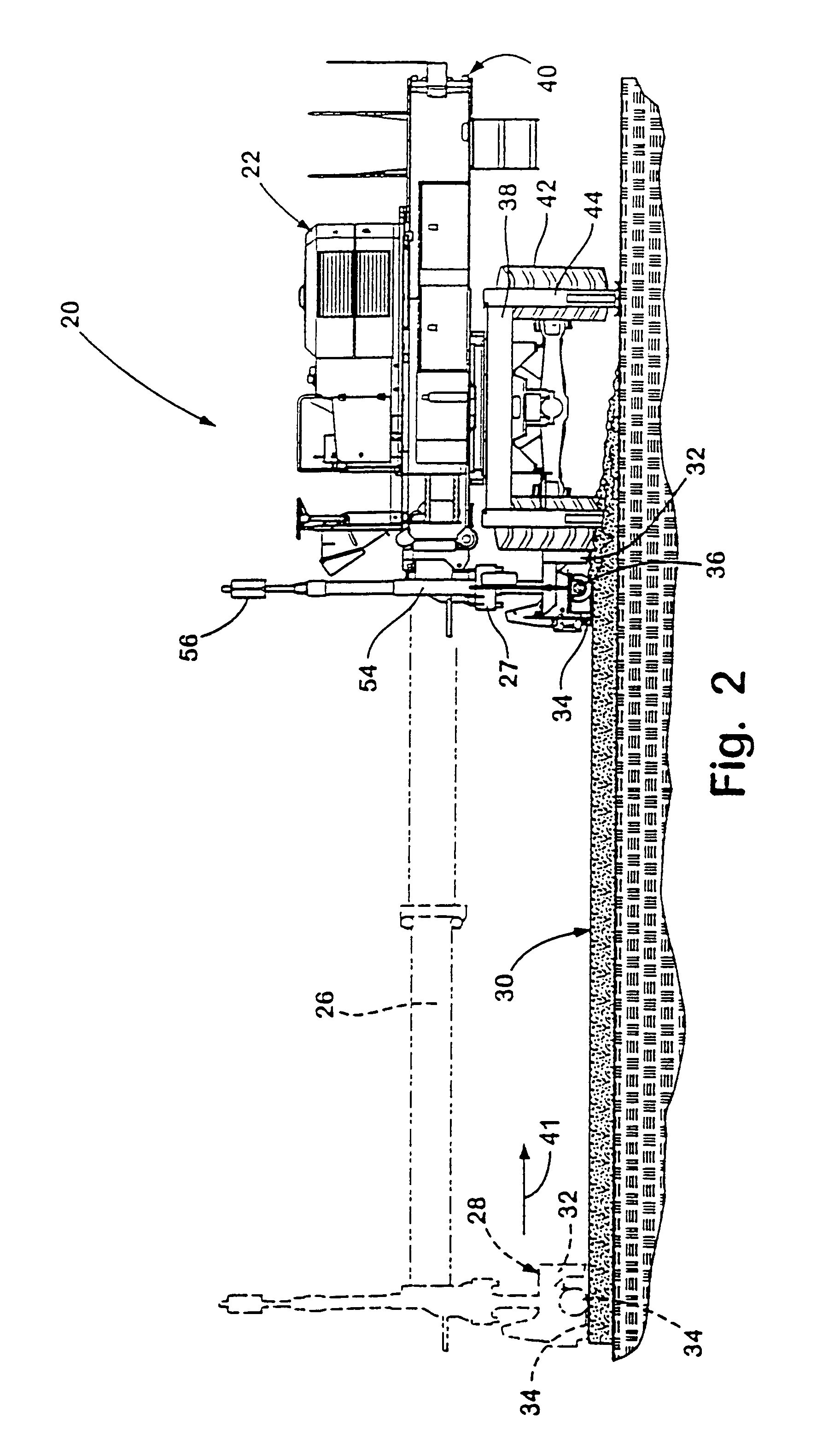
[0034]The present invention will now be described with reference to the accompanying drawings wherein like reference numerals correspond to like elements in the several drawings. A contouring device or machine 20 according to the present invention is depicted in FIG. 1. Contouring machine 20 includes a base 22 upon which an operator 24 controls contouring machine 20. Base 22 includes a platform 38 upon which an upper frame 40 is rotatably mounted. Base 22 can be moved to any desired location by wheels 42 which are powered by a motor onboard base 22. Platform 38 is securely planted at a desired location by four stabilizer legs 44 that are retractable when contouring machine 20 is driven to different locations. A boom 26 is telescopingly mounted on a front end of upper frame 40. A support beam 27 is affixed to boom 26 at an end opposite upper frame 40. A contouring member preferably includes a contouring assembly 28 mounted on support 27 by way of a right and left hydraulic cylinder 5...


PUM


Abstract

A device and method for contouring three-dimensionally curved surfaces includes an elongated contouring assembly that is supported at two locations by height adjustment mechanisms that raise and lower the two locations of the contouring assembly independently of each other. The contouring assembly creates a three-dimensionally curved surface as it passes over an area to be contoured. The control of at least one location of the contouring assembly is based on a comparison of the measured position of one portion of the contouring assembly with a profile of the surface to be leveled that is stored in a computer memory. Control of the height of the other location is preferably based on the height above a physical reference measured with a proximity sensor. A pivot or tilting controller may control the tilting of the contouring assembly to follow the slope of the profile stored in computer memory.

Description

CROSS-REFERENCE TO RELATED APPLICATIONS[0001]This application is a continuation of application Ser. No. 09 / 792,760, filed Feb. 21, 2001, which is a continuation of application Ser. No. 09 / 179,648, filed Oct. 27, 1998, now U.S. Pat. No. 6,227,761, issued May 8, 2001.BACKGROUND OF THE INVENTION[0002]This invention relates generally to methods and devices for contouring or smoothing freshly poured concrete, sand, gravel, dirt, or other like loose, spreadable materials, and, more particularly, to an apparatus and method for contouring and placement of such materials with a vehicle either positioned adjacent the materials to be contoured or driven through the materials to be contoured.[0003]In the past, the screeding or smoothing of uncured concrete by screeding machines has been primarily limited to flat, one or two dimensional surfaces. In order to screed a three dimensional concrete surface, the screeding apparatus was required to follow predetermined or preset forms, such as wires, b...

Claims


Application Information

Patent Timeline
Patent Type & Authority Patents(United States)
IPC IPC(8): E01C23/06E01C19/00E01C19/40
CPCE01C19/40E01C19/006
Inventor KIERANEN, CARL BHALLSTROM, CHARLES ASIMULA, GLEN RRUONAVAARA, NILS PWAINEO, JAMES D
Owner SOMERO ENTERPRISES INC
Learn More