Clamping unit with a platen hydrostatically supported on a frame element

a technology of hydrostatic support and platen, which is applied in the field of clamping units, can solve the problems of insufficient detection of malfunctions and particularly the effect of malfunctions, and achieve the effect of reducing the pressure of the hydrostatic suppor

Inactive Publication Date: 2008-07-15
KRAUSS MAFFEI KUMSTSTOFFTECHNIK GMBH
View PDF12 Cites 1 Cited by
  • Summary
  • Abstract
  • Description
  • Claims
  • Application Information

AI Technical Summary

Benefits of technology

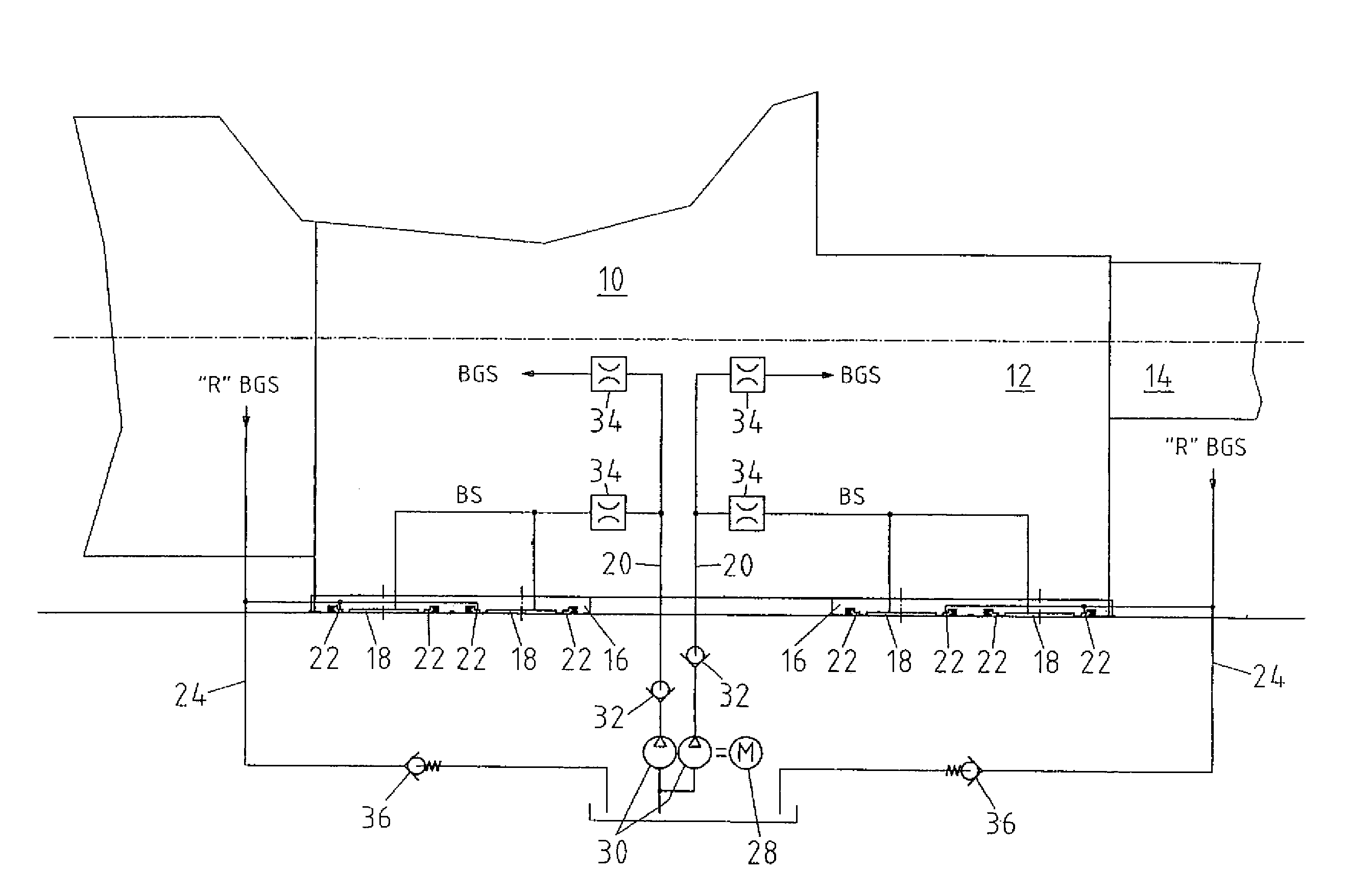
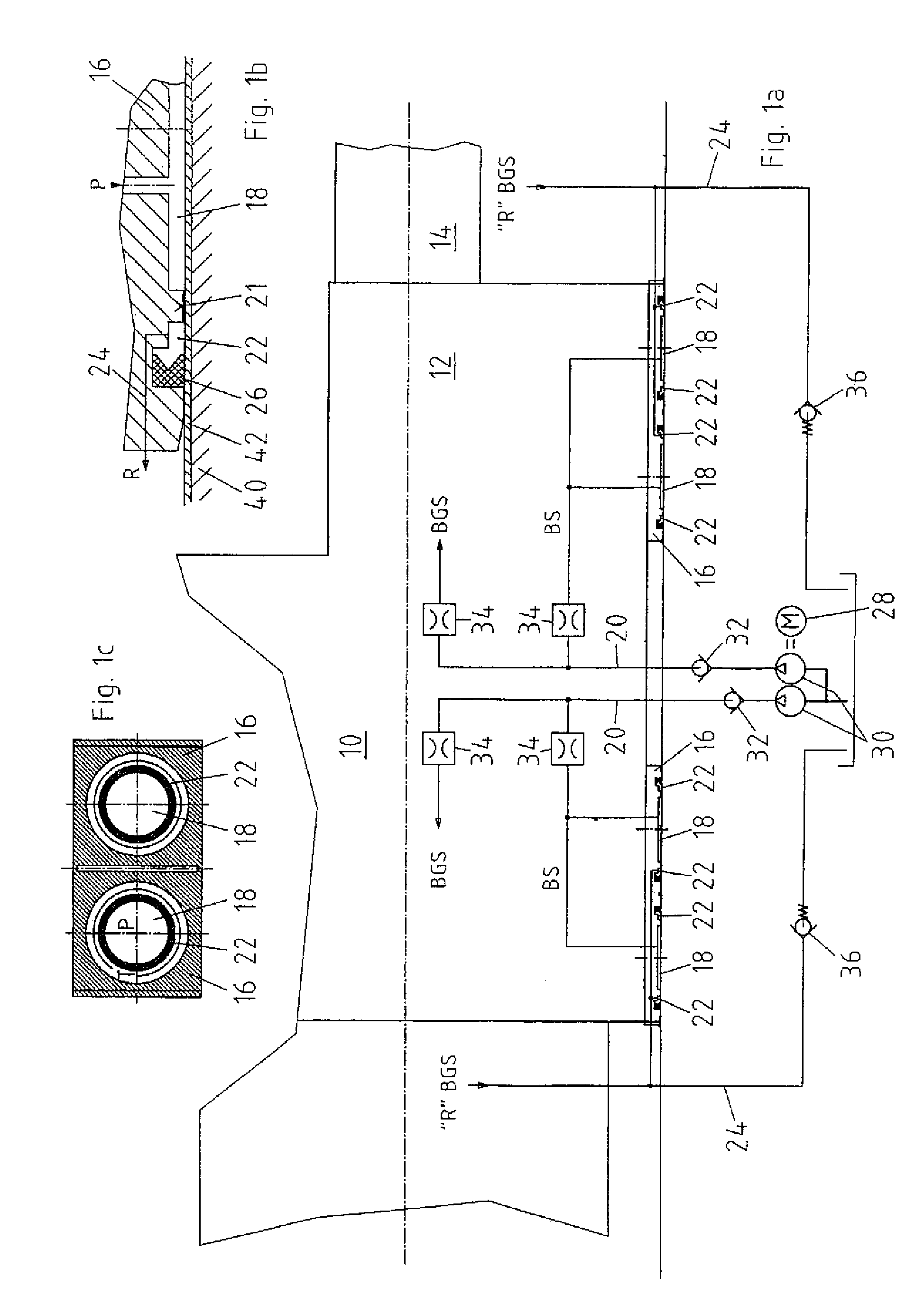
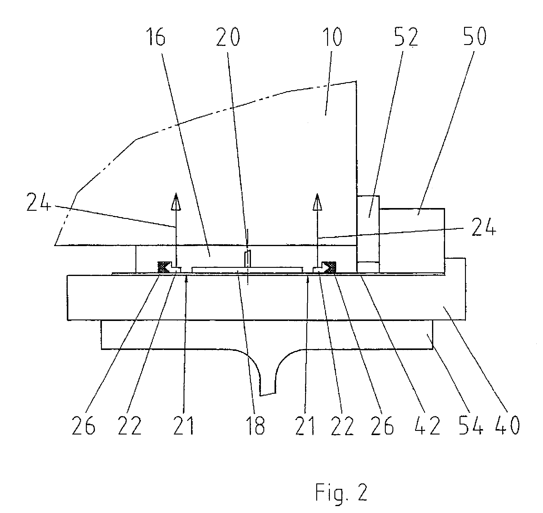
[0006]According to one aspect of the invention, a clamping unit, in particular for an injection molding machine, includes a frame element, at least one moving platen movably supported on the frame element, and at least one hydrostatic support formed between the moving platen and the frame element for facilitating back and forth displacement of the moving platen on the frame element.
[0007]As a consequence of the hydrostatic support produced at least during the travel motion of the moving platen, it is possible to maintain the friction between the moving platen and the frame element, on which the moving platen moves, at an almost constant low level, in particular independent from the movement speed of the platen. The force required to move the moving platen can then be kept small even at low speeds so that malfunctions—in particular those relating to safety—can be easily detected. The hydrostatic support is hereby implemented as a hydraulic support which is produced or can be produced also in a static state of the platen. During movement, the moving platen rests essentially on a “pad” of hydraulic fluid formed between the moving platen and the frame element. The “pad” can, of course, also be attained pneumatically. Accordingly, the term hydraulic should be broadly interpreted and includes also pneumatic fluids, such as air.

Problems solved by technology

This effect is particularly disadvantageous, when safety-related issues must be ascertained at the end of a closing movement.
Such safety-related issues may relate to a jamming of a not fully finished product between the two platens or a protrusion of a foreign object into the clamping unit.
In particular, when a slow end motion of the closing operation is involved, application of a greater force has been required heretofore as a result of the increase in friction, so that the sensitivity of the detection of malfunctions could not be sufficiently ensured.

Method used


Image

  • Clamping unit with a platen hydrostatically supported on a frame element
  • Clamping unit with a platen hydrostatically supported on a frame element
  • Clamping unit with a platen hydrostatically supported on a frame element

Examples


Embodiment Construction

[0030]Throughout all the Figures, same or corresponding elements are generally indicated by same reference numerals. These depicted embodiments are to be understood as illustrative of the invention and not as limiting in any way. It should also be understood that the drawings are not necessarily to scale and that the embodiments are sometimes illustrated by graphic symbols, phantom lines, diagrammatic representations and fragmentary views. In certain instances, details which are not necessary for an understanding of the present invention or which render other details difficult to perceive may have been omitted.

[0031]Turning now to the drawing, and in particular to FIG. 3, there is shown a conventional hydrodynamic support of a moving platen of a clamping unit. The moving platen 100 is illustrated in FIG. 3 only in a cross-section through the lower part. On the side of the mold, a slide shoe 110 is arranged adjacent to the moving platen 100 on each side of the support (only one slide...


PUM

PropertyMeasurementUnit
pressureaaaaaaaaaa
pressureaaaaaaaaaa
volume flowaaaaaaaaaa

Abstract

A clamping unit, particularly for an injection molding machine, includes at least one moving platen which is moveably arranged on a frame element. At least one hydrostatic support is provided in an area between the platen and the frame element for facilitating back and forth displacement of the moving platen to thereby avoid speed-dependent friction values. Operation of the clamping unit is realized by building up pressure in a hydrostatic support before the moving platen is initiated for displacement so that the moving plate is slightly raises platen in relation to the frame element. After displacement of the moving platen, the pressure in the hydrostatic support is decreased again.

Description

CROSS-REFERENCES TO RELATED APPLICATIONS[0001]This application is a continuation of prior filed copending PCT International application no. PCT / EP2005 / 053870, filed Aug. 5, 2005, which designated the United States and has been published but not in English as International Publication No. WO 2006 / 018400 and on which priority is claimed under 35 U.S.C. §120, and which claims the priority of German Patent Application, Serial No. 10 2004 040 194.2, filed Aug. 19, 2004, pursuant to 35 U.S.C. 119(a)-(d), the contents of which are incorporated herein by reference in its entirety as if fully set forth herein.BACKGROUND OF THE INVENTION[0002]The invention relates to a clamping unit, in particular for an injection molding machine.[0003]Nothing in the following discussion of the state of the art is to be construed as an admission of prior art.[0004]Clamping units, in particular for injection molding machines, typically include two platens for receiving molding tools, with at least one platen m...

Claims


Application Information

Patent Timeline
Patent Type & Authority Patents(United States)
IPC IPC(8): B29C45/64B29C45/17B30B15/04F16C29/02
CPCB29C45/1761F16C32/06F16C29/025
Inventor WOHLRAB, WALTER
Owner KRAUSS MAFFEI KUMSTSTOFFTECHNIK GMBH
Why Eureka
Try Eureka