Battery cooling structure
a battery and cooling structure technology, applied in the field of battery cooling structure, can solve the problems of reducing capacity, degrading durability, and difficulty in cooling, and achieve the effects of reducing dimensions, simplifying the battery case, and ensuring a degree of freedom in the layou
- Summary
- Abstract
- Description
- Claims
- Application Information
AI Technical Summary
Benefits of technology
Problems solved by technology
Method used
Image
Examples
first embodiment
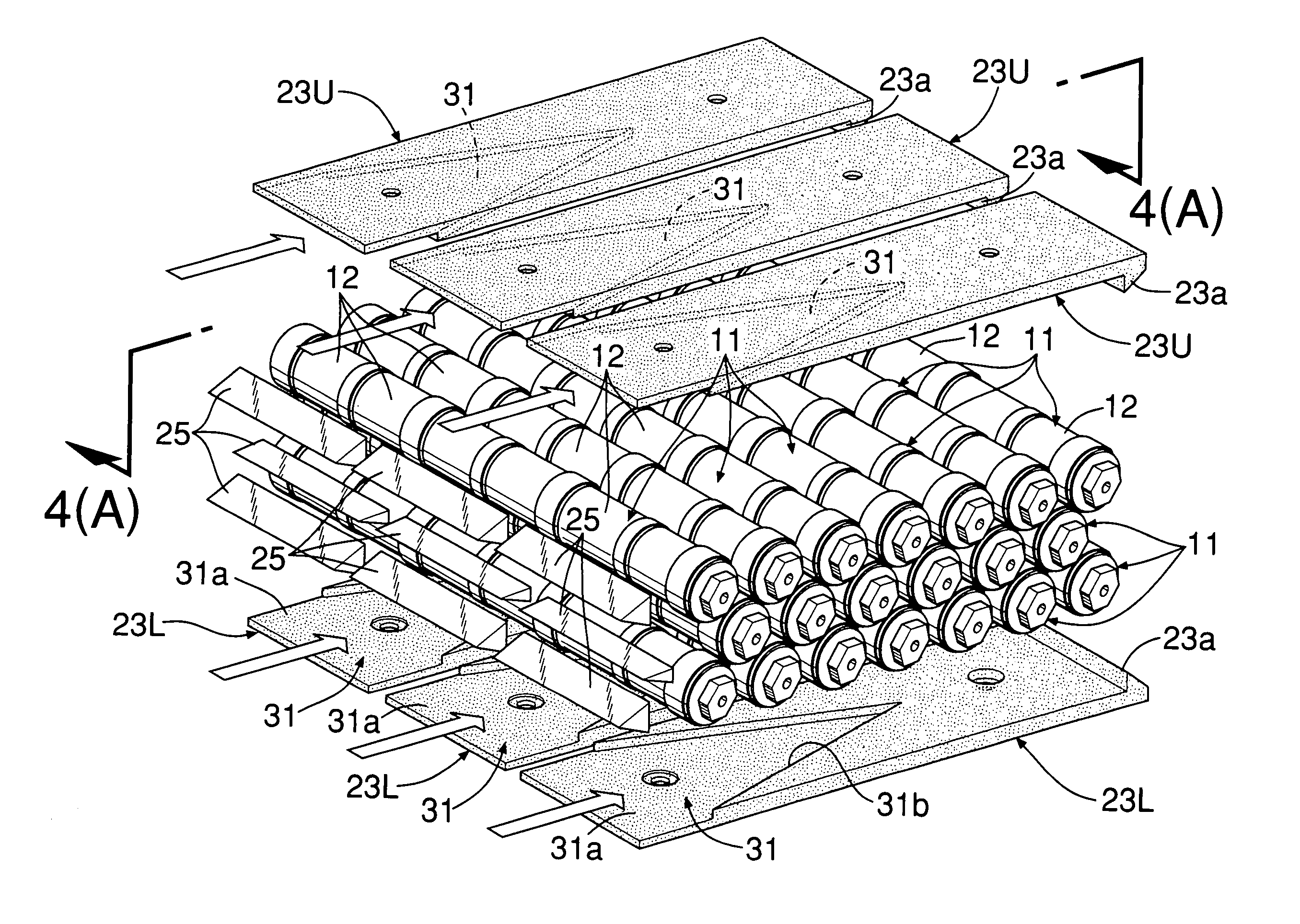
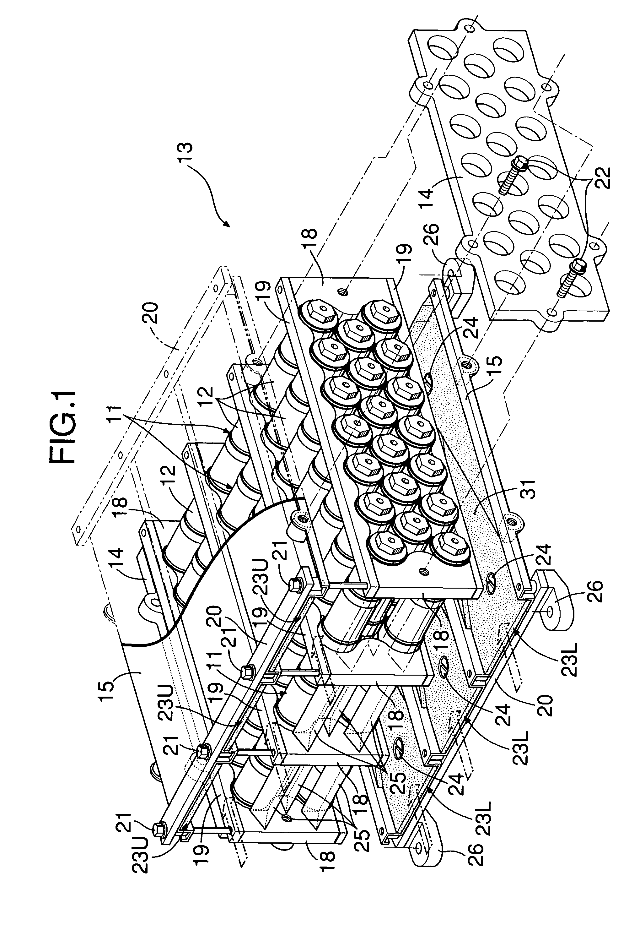
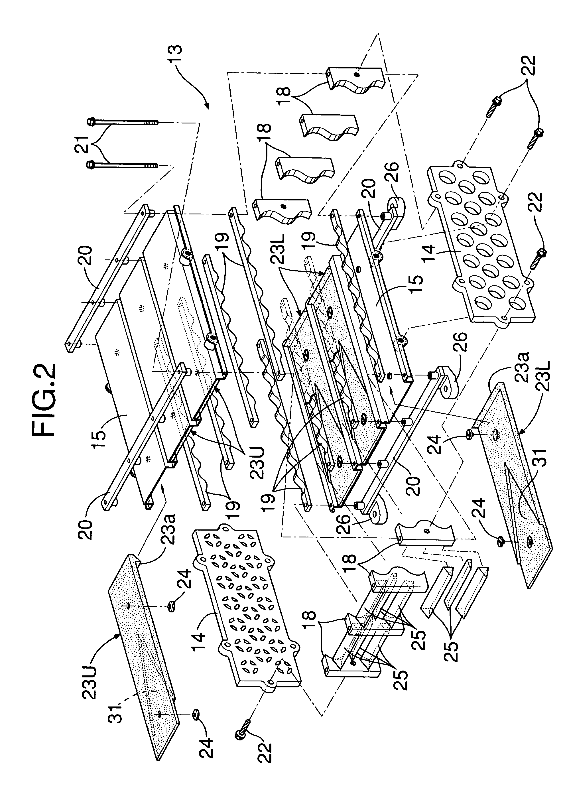
[0049]A first embodiment is now explained with reference to FIGS. 1 to 4C.
[0050]As shown in FIG. 1 and FIG. 2, a battery module 11, which serves as a power source for a hybrid vehicle motor / generator, is formed by integrally connecting together in series a plurality (six in this embodiment) of cylindrical battery elements 12 made of, for example, NiMH batteries into a rod shape, and twenty battery modules 11 are arranged in a staggered manner so that there are seven in an upper tier, six in a middle tier, and seven in a lower tier.
[0051]A battery case 13 for supporting the 20 battery modules 11 is made in the shape of substantially rectangular tube having a pair of rectangular first plates 14 forming left and right side faces of the battery case 13 and a pair of second plates 15 providing a horizontal connection between upper ends and between lower ends of the two first plates 14. Front and rear ends of the substantially rectangular tube-shaped battery case 13 are open; the front en...
fourth embodiment
[0067]FIGS. 7A, 7B, and 7C show the present invention. Deep cooling air guide channels 31 are formed so as to have a depth of 11 mm in upper air guide plates 23U, and shallow ones are formed so as to have a depth of 5.5 mm in lower air guide plates 23L. As a result, the flow rate of the cooling air blowing down from the cooling air guide channels 31 of the upper air guide plates 23U is higher than the flow rate of the cooling air blowing up from the cooling air guide channels 31 of the lower air guide plates 23L, thereby preventing the flow of cooling air from becoming sluggish in the vicinity of the battery modules 11 in the middle tier, to enhance the cooling effect.
[0068]As is clear from Table 1, in the fourth embodiment the maximum temperature of the battery module 11 in the middle tier of the third vertical row from the front, which had the highest temperature, was decreased to 52.1° C. and the temperature difference was decreased to 6.3° C.
fifth embodiment
[0069]FIGS. 8A, 8B, and 8C show the present invention, in which the position of the downstream ends of cooling air guide channels 31 of lower air guide plates 23L are displaced, relative to the downstream ends of cooling air guide channels 31 of upper air guide plates 23U, to the upstream side by a distance corresponding to the pitch at which battery modules 11 are arranged in the front-to-rear direction. Since the positions of the upstream ends of tapered portions 31b of the upper and lower cooling air guide channels 31 are the same, an angle V of the lower cooling air guide channels 31 is larger than an angle V of the upper cooling air guide channels 31. As a result, the position at which the cooling air blows down from the cooling air guide channels 31 of the upper air guide plates 23U is displaced from the position at which the cooling air blows up from the cooling air guide channels 31 of the lower air guide plates 23L, thereby preventing the cooling air from the upper directio...
PUM
| Property | Measurement | Unit |
|---|---|---|
| angle | aaaaa | aaaaa |
| temperature | aaaaa | aaaaa |
| temperature | aaaaa | aaaaa |
Abstract
Description
Claims
Application Information
 - R&D
- Intellectual Property
- Life Sciences
- Materials
- Tech Scout
- Unparalleled Data Quality
- Higher Quality Content
- 60% Fewer Hallucinations
Browse by: Latest US Patents, China's latest patents, Technical Efficacy Thesaurus, Application Domain, Technology Topic, Popular Technical Reports.
© 2025 PatSnap. All rights reserved.Legal|Privacy policy|Modern Slavery Act Transparency Statement|Sitemap|About US| Contact US: help@patsnap.com


