Phased array antenna system with variable electrical tilt

Inactive Publication Date: 2008-07-15
QUINTEL CAYMAN LTD
View PDF46 Cites 15 Cited by
  • Summary
  • Abstract
  • Description
  • Claims
  • Application Information

AI Technical Summary

Benefits of technology

[0050]Step d) may include providing for one set of divided signals to rise from a minimum to a maximum associated with the antenna array centre and its ends respectively, as appropriate to establish a progressiv

Problems solved by technology

Whereas an antenna's angle of mechanical tilt may be adjusted by re-positioning its radome, changing its angle of electrical tilt requires additional electronic circuitry which increases antenna cost and complexity.
The need for an individual angle of electrical tilt from a shared antenna has hitherto resulted in compromises in the performance of the antenna.
The boresight gain will decrease in proportion to the cosine of the angle of tilt due to a reduction in the effective aperture of the anten

Method used


Image

  • Phased array antenna system with variable electrical tilt
  • Phased array antenna system with variable electrical tilt
  • Phased array antenna system with variable electrical tilt

Examples


Embodiment Construction

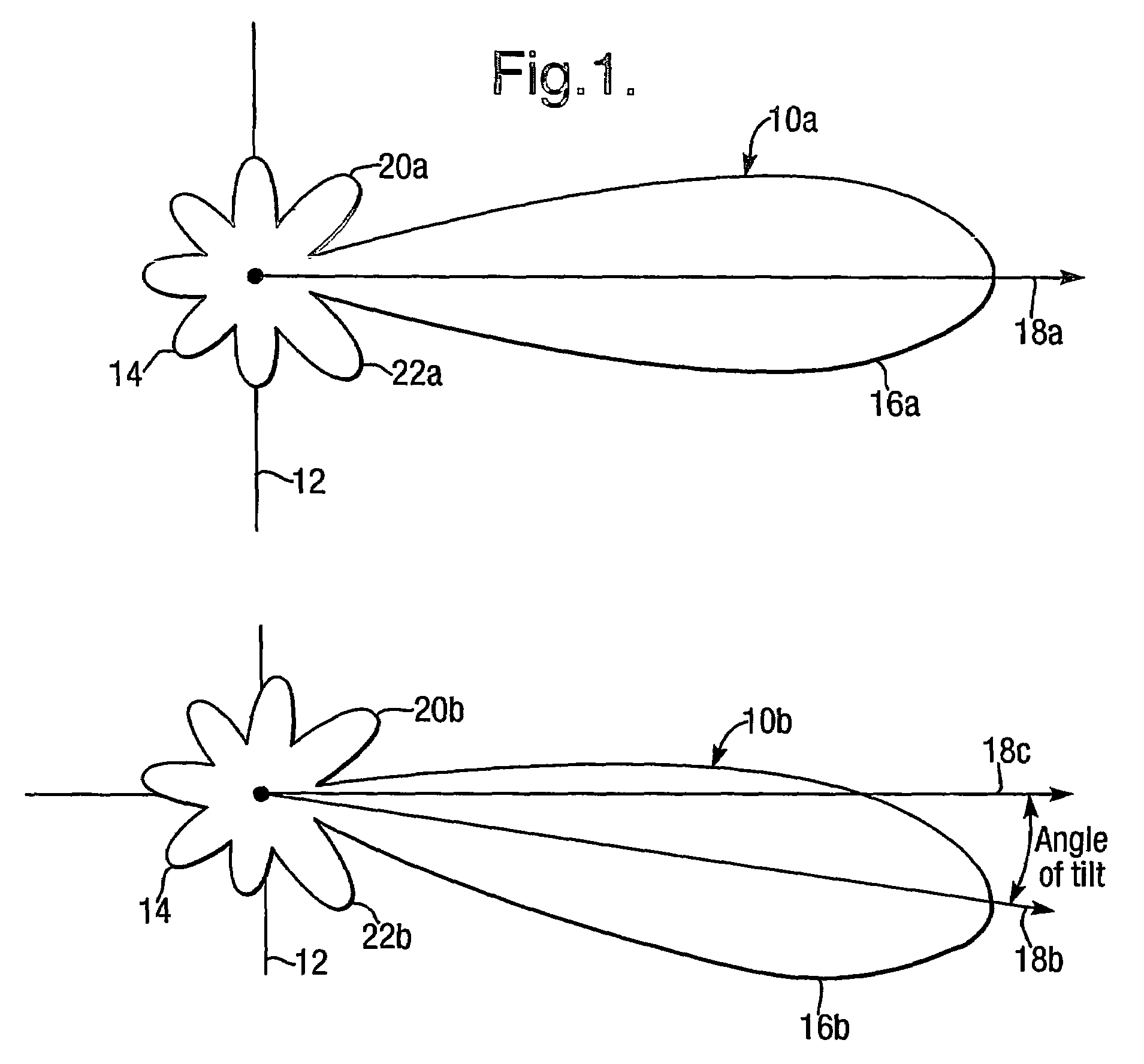
[0066]Referring to FIG. 1, there are shown vertical radiation patterns (VRP) 10a and 10b of an antenna 12 which is a phased array of individual antenna elements (not shown). The antenna 12 is planar, has a centre 14 and extends perpendicular to the plane of the drawing. The VRPs 10a and 10b correspond respectively to zero and non-zero variation in delay or phase of antenna element signals with array element distance across the antenna 12 from an array edge. They have respective main lobes 16a, 16b with centre lines or “boresights”18a, 18b, first upper sidelobes 20a, 20b and first lower sidelobes 22a, 22b; 18c indicates the boresight direction for zero variation in delay for comparison with the non-zero equivalent 18b. When referred to without the suffix a or b, e.g. sidelobe 20, either of the relevant pair of elements is being referred to without distinction. The VRP 10b is tilted (downwards as illustrated) relative to VRP 10a, i.e. there is an angle—the angle of tilt—between main b...


PUM


Abstract

A phased array antenna system with variable electrical tilt comprises an array (60) of antenna elements (60L1) etc. incorporating a divider (44) dividing a radio frequency (RF) carrier signal into two signals between which a phase shifter (46) introduces a variable phase shift. A phase to power converter (50) converts the phase shifted signals into signals with powers dependent on the phase shift. Power splitters (52, 54) divide the converted signals into two sets of divided signals with total number equal to the number of antenna elements in the array. Power to phase converters (561) etc. combine pairs of divided signals from different power splitters (52, 54) this provides vector sum and difference components with appropriate phase for supply to respective pairs of antenna elements (60U1, 60L1) etc. located equidistant from an array centre. Adjustment of the phase shift provided by phase shifter (46) changes the angle of electrical tilt of the antenna array (60).

Description

BACKGROUND OF THE INVENTION[0001](1) Field of the Invention[0002]The present invention relates to a phased array antenna system with variable electrical tilt. The antenna system is suitable for use in many telecommunications,systems, but finds particular application in cellular mobile radio networks, commonly referred to as mobile telephone networks. More specifically, but without limitation, the antenna system of the invention may be used with second generation (2G) mobile telephone networks such as the GSM system, and third generation (3G) mobile telephone networks such as the Universal Mobile Telephone System (UMTS).[0003](2) Description of the Art[0004]Operators of cellular mobile radio networks generally employ their own base-stations, each of which has at least one antenna. In a cellular mobile radio network, the antennas are a primary factor in defining a coverage area in which communication to the base station can take place. The coverage area is generally divided into a num...

Claims


Application Information

Patent Timeline
IPC IPC(8): H01Q3/00H01Q1/24H01Q3/36H01Q3/40H01Q25/00
CPCH01Q1/246H01Q25/00H01Q3/40H01Q3/36H01Q1/24
Inventor HASKELL, PHILIP EDWARD
Owner QUINTEL CAYMAN LTD
Why Eureka
Try Eureka