
Circuit breaking link status detection and reporting circuit

a technology of circuit breaking link and status detection, which is applied in the direction of electrical apparatus casing/cabinet/drawer, substation, coupling device connection, etc., can solve the problems of user inability to identify the circuit breaking link responsible for the open circuit, may violate the warranty of the unit, and the user may not be able to open the unit, so as to achieve the effect of large transmission capacity of layers

Active Publication Date: 2008-07-15
SERVER TECHNOLOGY
View PDF37 Cites 36 Cited by
  • Summary
  • Abstract
  • Description
  • Claims
  • Application Information

AI Technical Summary

Benefits of technology

[0025]Using an entire layer of a circuit board to transmit an electrical component may allow a larger amount of the electrical component, such as a component of AC line power, to be transmitted using the circuit board. The relatively large transmission capacity of the layers of the circuit board may allow the circuit board to function as an assembly of wires.
[0026]In at least one implementation, the circuit breaking link interconnection board includes at least one layer formed in a plurality of sublayers. An insulating barrier may separate each sublayer. Accordingly, each sublayer may be used to transmit a different electrical component, such as a component of AC line power or data. The use of a circuit breaking link interconnection board having a layer formed in a plurality of sublayers may allow the circuit breaking link interconnection board to have fewer layers, to transmit more electrical components, and / or be attached to a greater number of electrical parts. The size of the sublayer is preferably sufficiently large to allow effective transmission of the particular electric component.

Problems solved by technology

In addition to possibly being time consuming and labor intensive, opening up the unit may violate a warranty on the unit.
As the number of circuit breaking links increases, it may be more time consuming and difficult to identify the circuit breaking link responsible for the open circuit.
Additionally, a remote user may not be aware that a circuit has opened and the electrical devices are no longer receiving power from the power distribution unit.

Method used


Image

  • Circuit breaking link status detection and reporting circuit
  • Circuit breaking link status detection and reporting circuit
  • Circuit breaking link status detection and reporting circuit

Examples


Embodiment Construction

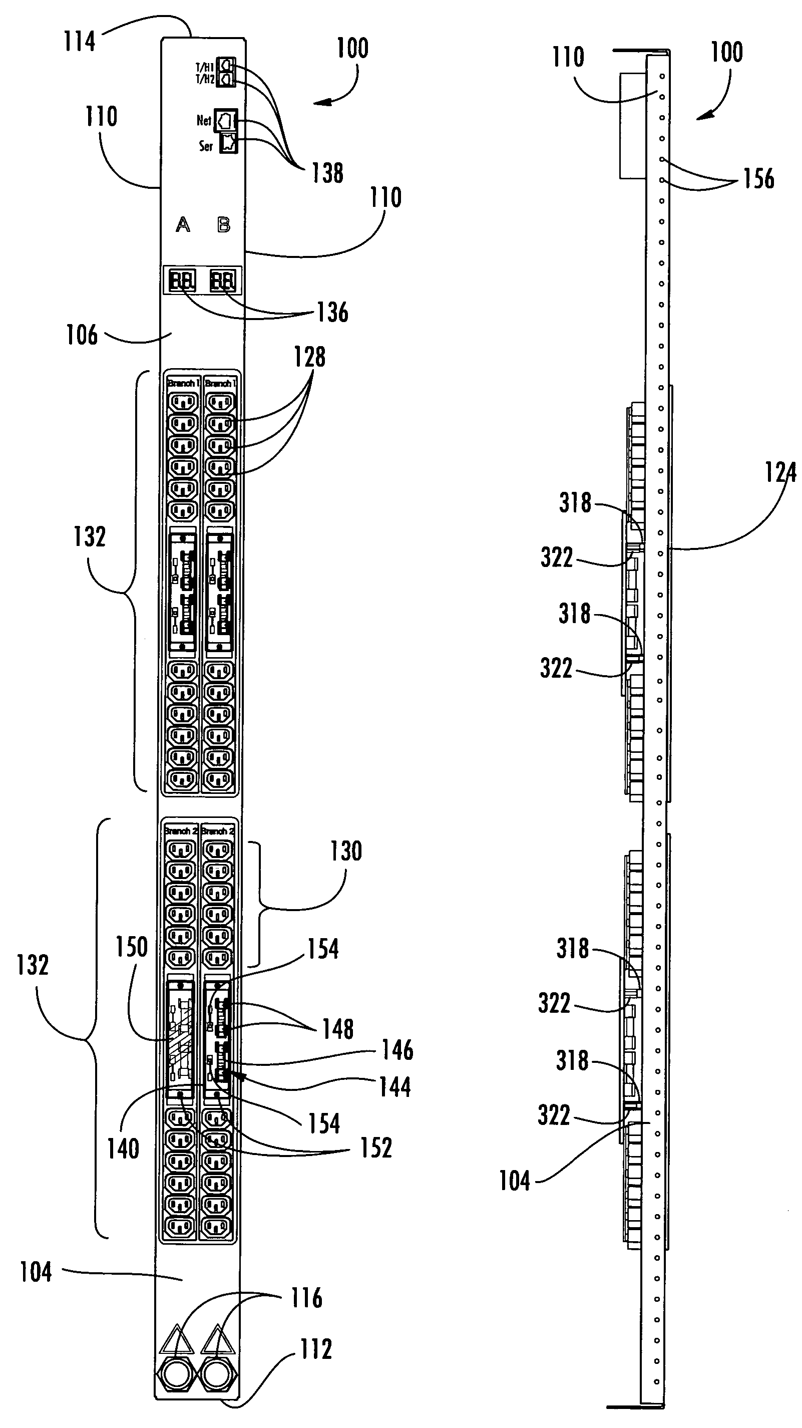
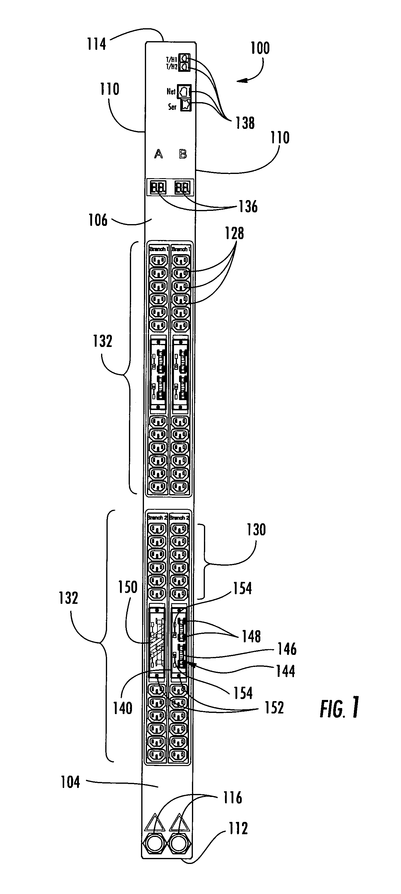
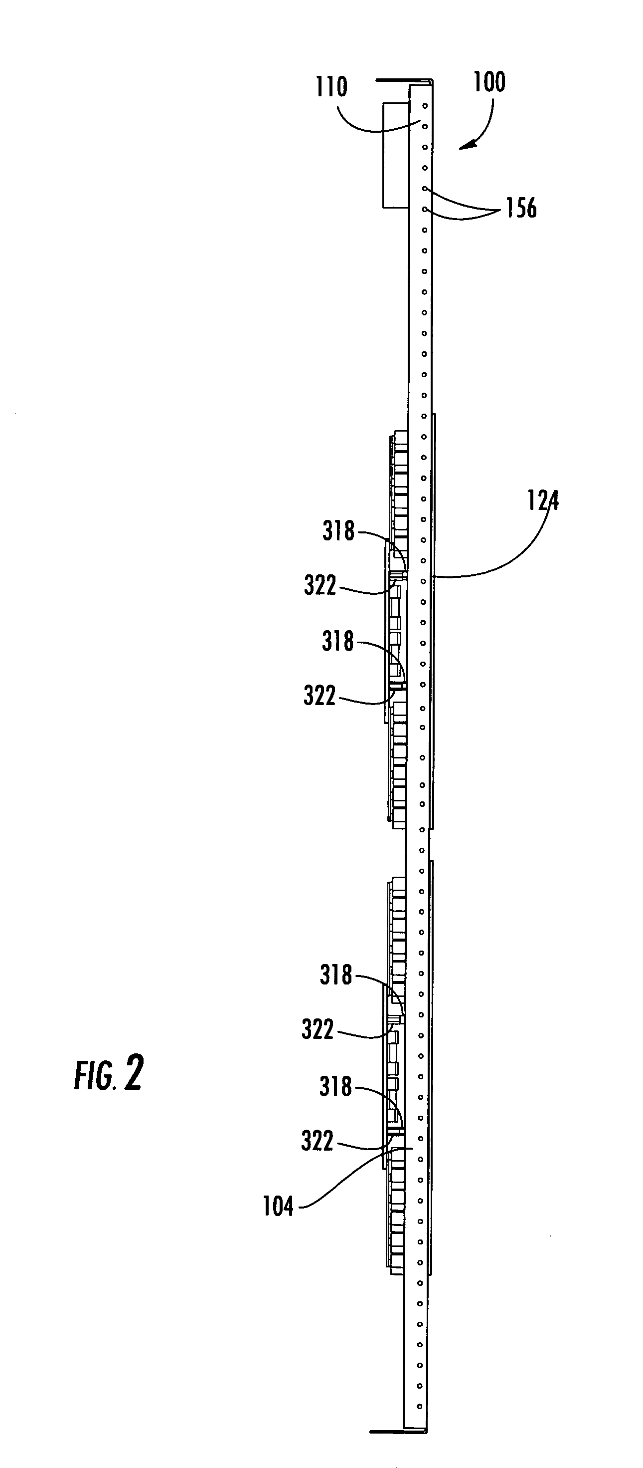
[0040]A power distribution apparatus (PDA) 100 according to an embodiment of the present invention is shown in FIG. 1. The PDA 100 may be mounted to a rack (not shown). The PDA 100 has a housing 104. The housing 104 may be of any suitable dimensions. The housing 104 is preferably sized for mounting to a rack. The housing 104 is shown as a rectangular box having longitudinally extending front 106 and back 108 (FIG. 3) faces, two longitudinally extending lateral sides 110, a first end 112, and a second end 114. Of course, shapes other than rectangular boxes could be used.

[0041]The housing 104 is made of a substantially rigid and durable material, such as metals or plastics, including polycarbonate resins. In at least one embodiment, the housing 104 is made of sheet metal.

[0042]Two power inputs 116 are coupled to the housing 104. Although two power inputs 116 are shown, more or less power inputs 116 could be used. In the illustrated embodiment, the power inputs 116 are connected throug...


PUM


Abstract

Certain embodiments provide a circuit breaking link status and reporting system. The system includes a power source and a circuit breaking link in communication therewith. An electrical outlet is in interruptible power supply communication with the circuit breaking link. A sensor is in interruptible electrical communication with the circuit breaking link and configured to generate a signal indicating whether the circuit breaking link is open. A local processor communicates with the sensor and is configured to determine whether the circuit is open. A communications bus is in communication with the local processor and configured to receive signals from the local processor. A processor is in communication with the local processor through the communications bus and configured to receive information regarding the status of the circuit breaking link. A communications port is in communication with the processor and configured to send information regarding the status of the circuit breaking link over a network.

Description

CROSS REFERENCE TO RELATED APPLICATIONS[0001]The present application claims, the benefit of, and hereby expressly incorporates by reference in its entirety, U.S. Provisional Patent Application No. 60 / 624,286, filed Nov. 1, 2004, and entitled “POWER DISTRIBUTION APPARATUS”, By Ewing et al.TECHNICAL FIELD[0002]The present invention relates to methods and systems for reporting the status of a circuit breaking link. Certain embodiments provide power distribution apparatus utilizing a circuit breaking link connector and which reports the status of the circuit breaking link connector.BACKGROUND[0003]Electronic equipment racks commonly consist of rectangular or box-shaped housings or rack structures. Electronic equipment is commonly mountable in such racks so that the various electronic components are aligned vertically one on top of the other in the rack. Often, multiple racks are oriented side-by-side, with each rack containing numerous electronic components and having substantial quanti...

Claims


Application Information

Patent Timeline
Patent Type & Authority Patents(United States)
IPC IPC(8): H02B1/26H01R13/46
CPCH01R25/00H01H85/30H01R13/641H01H85/32
Inventor EWING, BRANDON W.CLEVELAND, ANDREW J.MASKALY, JAMES P.MCGLUMPHY, DENNIS W.AUCLAIR, BRIAN P.
Owner SERVER TECHNOLOGY
Learn More