Apparatus for removing surface coverings and methods for using such apparatus

a technology for removing surfaces and apparatuses, applied in the direction of oven incrustation prevention/removal, hollow article cleaning, manufacturing tools, etc., can solve the problems of not being able to raise any one flap of a shingle in order to gain access to fasteners, and affecting the use of the roof. , to achieve the effect of increasing the size of the roof, and reducing or minimizing fatigu

Inactive Publication Date: 2008-07-22
PURCELL PATRICK W
View PDF42 Cites 8 Cited by
  • Summary
  • Abstract
  • Description
  • Claims
  • Application Information

AI Technical Summary

Benefits of technology

[0014]A need has arisen for an apparatus for removing surface coverings and methods for using such apparatus, which provide sufficient leverage, such that the apparatus reduces or minimizes fatigue to the user. This advantage is especially desirable as the size of the roof increases, from which a roofer must remove a layer or layers of shingles using the apparatus. It is a further advantage of this apparatus and method that they may be employed with a reduced or minimized amount of expended energy by the user.
[0015]A further need has arisen for an apparatus for removing surface coverings, which may efficiently and rapidly remove surface coverings, e.g., a layer or layers of shingles, from building roofs and sides. A still further need has arisen for an apparatus for removing surface coverings, e.g., a layer or layers of shingles, which allows the shingles and securing fasteners to be lifted simultaneously.
[0016]Yet a further need has arisen for an apparatus for removing surface coverings, e.g., a layer or layers of shingles, which may be easily manipulated and safely handled by a single roofer even when employed on a pitched roof of a building. The apparatus preferably is sturdy, simple to control and maneuver, and relatively lightweight. Consequently, the apparatus is preferably readily portable and may be powered by convenient sources of energy, such as compressed air, thereby enabling the apparatus to be used in numerous environments.

Problems solved by technology

Over time, roofing shingles wear out, deteriorate, or suffer damage and lose their effectiveness.
When the shingles wear out or deteriorate, that is, when the surface granulation thereof has worn off, or if the roof becomes damaged due to storms, a second layer of shingles may be laid over the existing shingles.
Because these succeeding shingles are fastened, e.g., nailed or stapled, and held down in the same manner, it may not be possible to merely raise any one flap of a shingle in order to gain access to the fasteners.
To remove the shingles, problems arise in obtaining access to the fasteners.
To obtain access to the fasteners and to pry the fasteners up on a fastener-by-fastener, especially, if two layers of shingles are on the roof surface, may be extremely time consuming.
During removal the shingles often split or rip, littering the shingled surface with debris which must be removed before a new protective surface may be applied.
Withdrawing the old roofing fasteners or driving them into the roof surface increases the total required time for removal of the old roofing materials and installation of the new roofing materials, thereby increasing the total cost of the roofing replacement operation.
Proper preparation of an existing roof for replacement shingle installation may be a difficult and time consuming job.
Such tools are often cumbersome to operate, and their use may result in wasted man hours.
The steep and often dangerous pitch of known roofs further aggravates the problems encountered in removing shingles with known hand tools.
Such pry bars, however, tend to deform or break.
Moreover, such manual removal processes are tedious, repetitive, laborious, and exhaustive.
Repetitive bending or lifting and remaining in awkward postures for prolonged periods, however, may tire back muscles and result in ligament sprains.
Sprains occur when back muscles are no longer able to respond to repetitive movements.
Removing roofing materials by means of such known hand tools may increase significantly the likelihood of back injury.
While powered, shingle removing tools have been proposed, such tools have suffered from various drawbacks in actual practice.
Thus, for example, some such removal tools have not provided appropriate leverage or mechanical advantage at the tip edge of the blade to quickly and conveniently remove shingles.

Method used


Image

  • Apparatus for removing surface coverings and methods for using such apparatus
  • Apparatus for removing surface coverings and methods for using such apparatus
  • Apparatus for removing surface coverings and methods for using such apparatus

Examples


Embodiment Construction

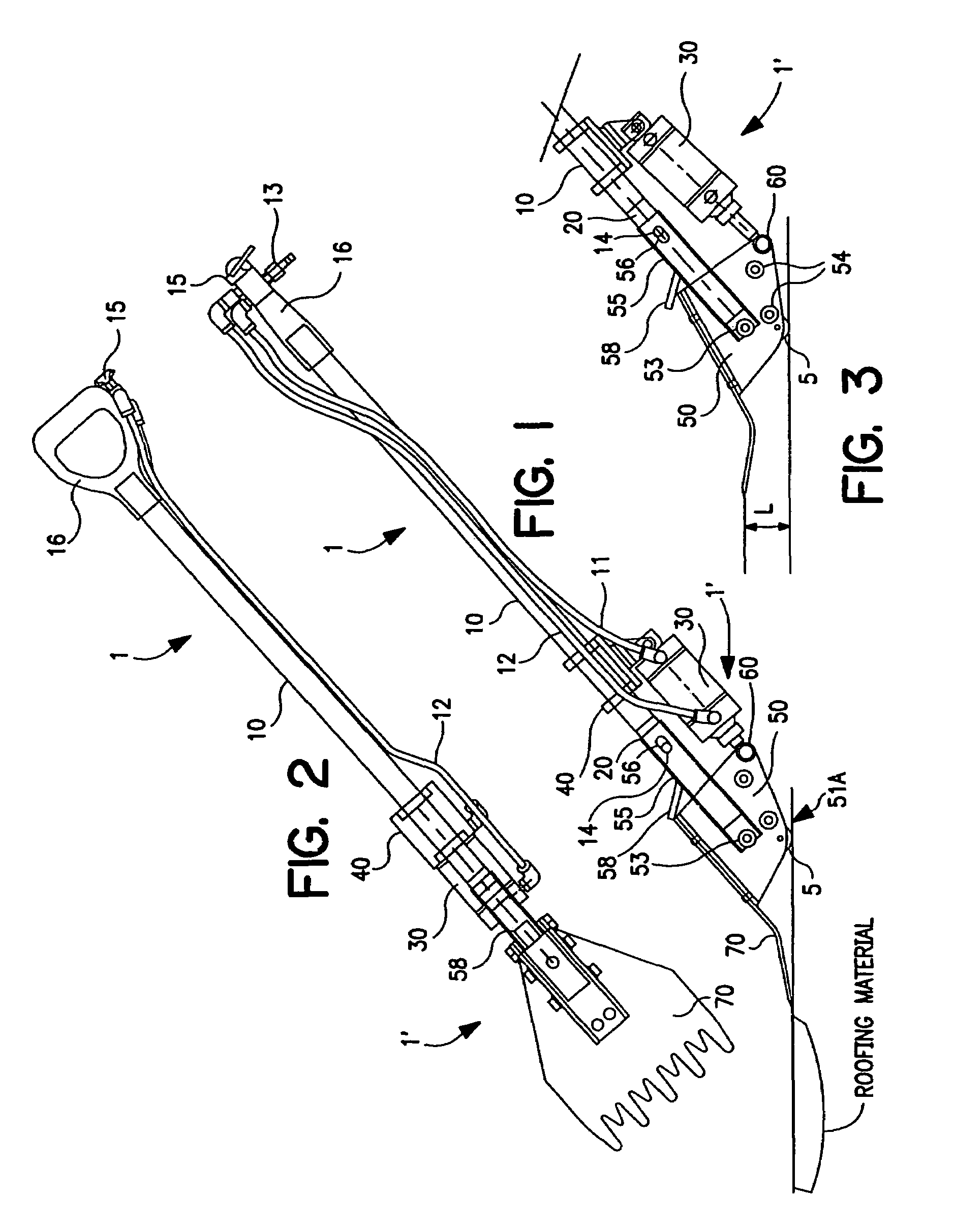
[0038]FIGS. 1-10 depict embodiments of the invention. Like numerals are used to identify the same or similar elements in each embodiment.

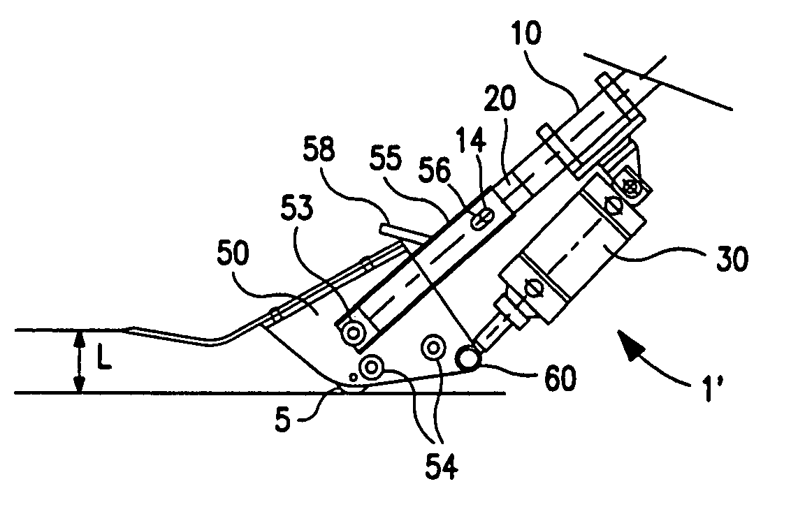
[0039]FIG. 1 is a side view of an apparatus 1 for removing surface coverings, according to an embodiment of the present invention. This figure depicts a view of apparatus 1 as a roofer would position it to remove roofing materials, comprising a blade 70, which pivots on a fulcrum 51A, at which a blade clevis 50 contacts the building surface. In addition, clevis 50 may comprise means for traversing the building surface with reduced friction or frictionlessly, such as a roller 5, disposed at or proximate to fulcrum 51A. A switch 15, such as a finger operated, directional control valve, is mounted to a handle 16 and connected to a second end of shaft 10 and via shaft 10 to a working head 1′ of apparatus 1. In FIG. 9, another embodiment of a handle 916 and a lever switch 915, such as a dead man's switch, is depicted.

[0040]Referring to FIG. 3, working h...


PUM

PropertyMeasurementUnit
diameteraaaaaaaaaa
distanceaaaaaaaaaa
lengthaaaaaaaaaa

Abstract

A apparatus for removing surface coverings, includes a shaft having a first end and a second end; a sleeve slidably mounted on the first end of the shaft; a clevis pivotably mounted on a first end of the sleeve; a drive mechanism for shifting a rod between a first rod position and a second rod position relative to the shaft; and a blade mounted on the clevis and extending away from the shaft. The clevis is secured to the rod, such that as the rod moves between the first rod position and the second rod position, the clevis pivots on the sleeve, and the sleeve slides on the shaft to shift a leading edge of the blade between a first edge position and a second edge position.

Description

[0001]This application claims the benefit of U.S. Provisional Patent Application No. 60 / 464,432, filed Apr. 23, 2003, which is incorporated herein by reference.BACKGROUND OF THE INVENTION[0002]1. Field of the Invention[0003]The invention relates to an apparatus for removing surface coverings and methods for using such apparatus. More particularly, it relates to powered apparatus for removing surface coverings from roofs, including inclined or flat roofs, or from the sides of buildings, or both. Still more particularly, the present invention relates to apparatus having a double-acting cylinder powered by compressed air for removing surface coverings from roofs or from the sides of buildings, or both.[0004]2. Description of Related Art[0005]The exterior surfaces of buildings may be covered with a plurality of overlapping, horizontally aligned rows of shingles. The first row of shingles generally is laid across the lowermost edge of the surface to be covered and fastened, e.g., nailed ...

Claims


Application Information

Patent Timeline
Patent Type & Authority Patents(United States)
IPC IPC(8): E21C25/00E04D15/00E04F21/20
CPCE04F21/20E04D15/003
Inventor PURCELL, PATRICK W.MILLER, KEVIN J.
Owner PURCELL PATRICK W
Why Eureka
Try Eureka