Connector system having a connection detecting mechanism

a detection mechanism and connection technology, applied in the direction of connection, electrical apparatus, coupling device connection, etc., can solve the problems of difficult to detect securely the engagement of the lock projection and the lock arm

Active Publication Date: 2008-07-22
YAZAKI CORP
View PDF8 Cites 30 Cited by
  • Summary
  • Abstract
  • Description
  • Claims
  • Application Information

AI Technical Summary

Benefits of technology

[0018]According to the invention, since there are almost no position shifts between the shorting member, the contact point of one electrode and the lock projection along the direction of fitting connector housings, even if the shorting member is slightly deformed into the unexpected shape, the shorting member securely shorts the pair of electrodes to each other when the lock projection and the lock arm are engaged normally, and the shorting member does not shorts the pair of electrodes to each other when the lock projection and the lock arm are not engaged normally. Thereby, even if the shorting member is slight deformed, connection or disconnection of the connector housings is securely detected. Thus, connection of the connector housings to each other can be exactly detected.
[0019]According to the invention, since it can limit the shorting member to be affected when the lock arm is deformed, the shorting member can short securely the pair of electrodes to each other while the deformed lock arm is engaged with the lock projection. Therefore, when the lock arm is engaged with the lock projection even if the lock arm is deformed, a short break of the pair of electrodes caused by moving the shorting member apart from the pair of electrodes is prevented.
[0020]According to the invention, since the interlocked-deforming mechanism move the shorting member apart from the pair of electrodes when the lock arm rides on the lock projection, the shorting member does not short the pair of electrodes until the connector housings are completely fitted to each other.
[0021]Since the interlocked-deforming mechanism allows the shorting member to abut on the pair of electrodes when the lock arm is engaged with the lock projection, the shorting member can short the pair of electrodes when the connector housings are completely fitted to each other.
[0022]Thereby, the connection or disconnection of the connector housings can be securely detected.
[0023]According to the invention, the connector housings can be securely fitted and the pair of electrodes can be securely shorted with the shorting member by rotating the rotating lever.

Problems solved by technology

Thus, according to the connector shown in Patent Document 1, since the shorting member, the pair of electrodes and the lock projection are arranged at positions shifted to each other along the direction of fitting the connector housings, it is difficult to detect securely engagement of the lock projection and the lock arm.

Method used


Image

  • Connector system having a connection detecting mechanism
  • Connector system having a connection detecting mechanism
  • Connector system having a connection detecting mechanism

Examples


first embodiment

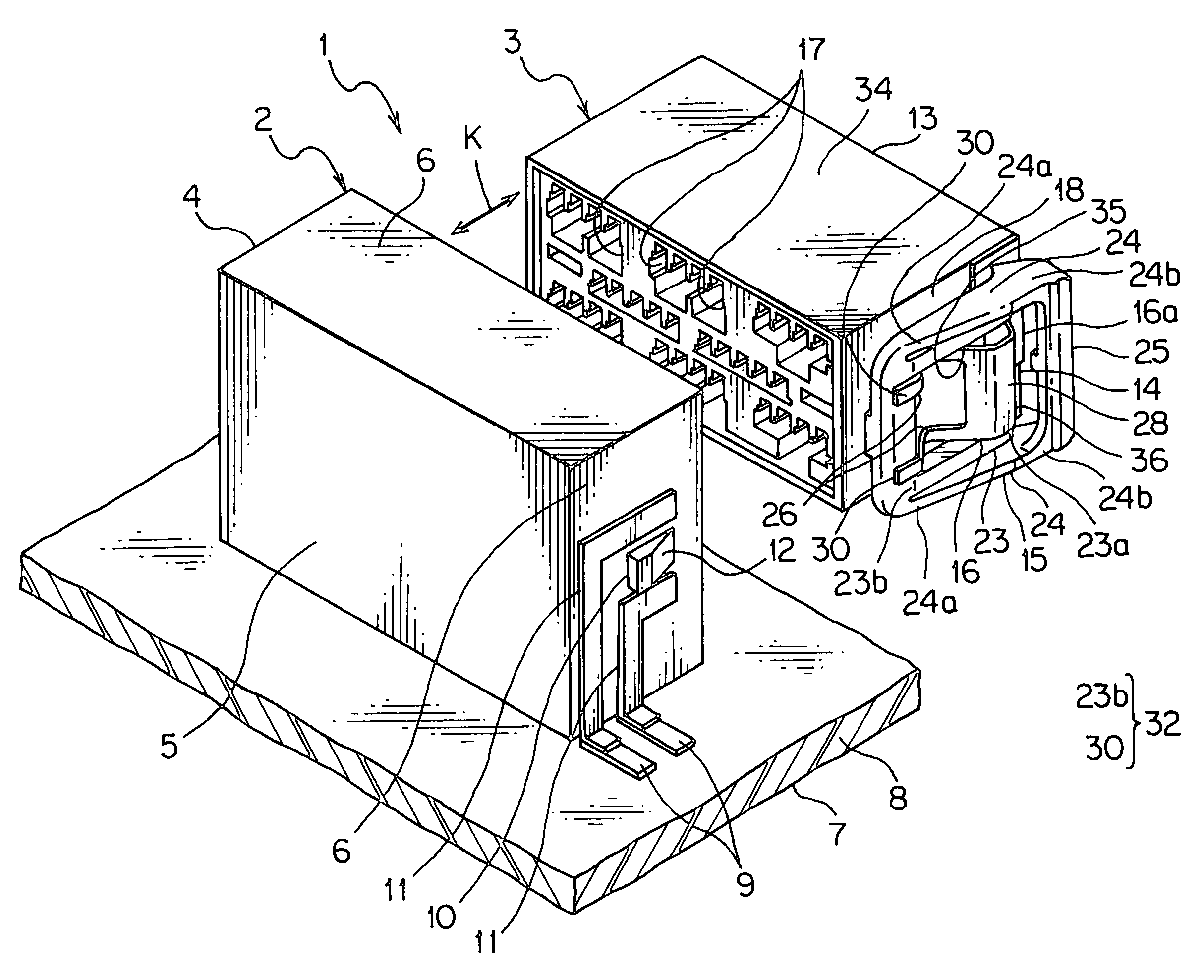
[0038]A connector system of a first embodiment according to the present invention will be described with reference to FIGS. 1-6. The connector system 1 includes a first connector 2 and a second connector 3.

[0039]The first connector 2 has a first connector housing 4 and a terminal (not shown). The first connector housing 4 is made of insulating synthetic resin, and formed into a bottomed box shape with a bottom wall 5 and a plurality of surround walls 6 extending perpendicularly from outer edges of the bottom wall 5. The first connector housing 4 is mounted on a printed circuit board 7 so as to pile the one surround wall 6 on the printed circuit board 7.

[0040]The printed circuit board 7 has an insulating base board 8 and a conductive wiring pattern 9 formed on the base board 8 (a part of the wiring pattern 9 is shown in FIG. 1 and the other thereof is omitted). The wiring pattern 9 includes a connection detecting circuit for detecting whether or not the connectors 2, 3 are completely...

second embodiment

[0087]Effects of locating the lock arm 15, which is provided at the rotating lever 33 mounted on the second connector 3, outside the first connector housing 4 is evaluated. The result is shown in FIGS. 10, 11. FIG. 10 is an illustrated view of the second connector 3 of the connector system 1 according to the The second connector 3 moves in order at positions shown with a long dashed double-short dashed line and with a long dashed short dashed line in FIG. 10 against the first connector 2. When the second connector 3 is fitted with the first connector 2, the second connector 3 is positioned at a position shown with a solid line in FIG. 10.

[0088]FIG. 11 is an illustrating view showing an example for comparing, in which the lock projection 10 is provided at the lock arm 15, and the lock hole 35 is provided at the surround wall 6 of the first connector housing 4, and the lock arm 15 is located inside the first connector housing 4 after fitting the connector housings 4, 13 to each other...


PUM


Abstract

Providing a connector system, which can detect securely connection of connector housings, the connector system includes a first connector and a second connector. The first connector includes a first connector housing, on an outer surface of which a lock projection and a pair of electrodes are provided. The second connector includes a second connector housing having a main body, a lock arm and a shorting member. The lock arm supported by the main body is engaged with the lock projection. One end portion of the shorting member is mounted on the main body, and the other end is formed like a free end of a cantilever. The other end has a contact point. When the connector housings are fitted together, the contact point and lock projection are arranged in a direction perpendicular to a fitting direction.

Description

[0001]The priority application Number Japan Patent Application 2005-263772 upon which this patent application is based is hereby incorporated by reference.BACKGROUND OF THE INVENTION[0002]1. Field of the Invention[0003]This invention relates to a connector system for connecting electric wires.[0004]2. Description of the Related Art[0005]Various electronic devices are mounted in a car as a vehicle. Wiring harnesses are wired in the car for transmitting electric power and control signals to the electronic devices. Each wiring harness includes a plurality of electric wires and a plurality of connectors (refer Patent Document 1). The electric wire has a conductive core wire and an insulating cover for covering the core wire, that is a covered wire.[0006]The connector described in Patent Document 1 includes a first connector housing having a pair of electrodes for detecting connection and a lock arm and a lock projection on an outer surface thereof an a second connector housing having a ...

Claims


Application Information

Patent Timeline
Patent Type & Authority Patents(United States)
IPC IPC(8): H01R13/627
CPCH01R13/6275H01R31/08H01R13/641H01R13/703
Inventor OHTAKA, KAZUTOTAKAHASHI, TOSHIHARUTANAKA, SHIGERU
Owner YAZAKI CORP
Why Eureka
Try Eureka