Multiphase clock recovery

a multi-phase clock and recovery technology, applied in the field of communication systems and digital clock recovery, can solve the problems of clock recovery mechanism, imposing unnecessary restrictions on input data variation, and difficult task of aligning a sample clock to the incoming data, so as to reduce the sensitivity to abnormal input data conditions and limit the impact of perturbations

Active Publication Date: 2007-01-11
TELEFON AB LM ERICSSON (PUBL)
View PDF5 Cites 35 Cited by
  • Summary
  • Abstract
  • Description
  • Claims
  • Application Information

AI Technical Summary

Benefits of technology

[0018] The entire decision logic is hence preferably distributed and transferred down to individual control units and building blocks operating independently of each other. The overall dynamic clock selection is conveniently performed completely in parallel by the individual control units, each of which acts as a gatekeeper to a unique sample clock phase. In this way, the clock recovery system only requires small, low complexity building blocks, as opposed to a conventional centralized phase selection topology, which generally requires a far more complex overall control and supervision logic. The building blocks of the clock recovery system may be implemented as synchronous or asynchronous state machines without any limitation.
[0019] The parallel transition indication information is hence not terminated by any centralized control mechanism in the usual increment / decrement manner associated with feedback-based clock synthesis. Instead, the all-through parallelism of the clock recovery mechanism proposed by the invention makes the clock recovery system virtually insensitive to input data history, in contrast to feedback-based clock recovery systems that are input pattern and sequence sensitive. As should be understood, there is no clock domain or reference phase associated with the clock selection process. In addition, the clock recovery mechanism according to a preferred embodiment of the invention provides instantaneous resynchronization upon every input data transition, without any black out periods and delay sensitive feedback-based information processing. For the same reason, other advantages include limited impact of perturbations and reduced sensitivity to abnormal input data conditions. Data jitter frequencies up to the bit rate can be followed in jitter tracking mode. Edge to edge varying jitter is not in general averaged since a new sample phase selection decision is taken in response to every input data transition.

Problems solved by technology

Unfortunately Non Return to Zero (NRZ) encoding is widely used, which in turn does not prevent long sequences of marks (logical high state or one) or zeros (logical low state or zero) in a row.
Aligning a sample clock to the incoming data is thus a difficult task when there is little synchronization information (edge transitions) available due to NRZ type of coding schemes.
Conventional accurate data receivers designed to operate without malfunction over a wide range of conditions are often sensitive to excessive input data cycle-to-cycle variations.
Severe limitations in the clock recovery mechanism tend to impose unnecessary restrictions on the input data variation.
Common practice of clock recovery is to employ a resonant circuit, often denoted a Q-tank, which has good filtering characteristics but also give rise to a large amount of jitter when the resonant circuit is left unaided between the data transitions (drift towards the natural resonant frequency).
Naturally a more precisely tuned Q-tank has a resonant frequency, which is at least closer to the ideal source clock frequency, but there is always a residual frequency drift (due to source tolerances) especially with NRZ coded data that is not rich in the transitions necessary to guide the resonant circuit properly.
Note also that a low loss (high Q) resonator has a very narrow band of acceptable input frequencies and thus may reject an offseted source totally with a significantly reduced flexibility at hand.
High frequency jitter on the input data signal cannot be tracked (followed) which pose a limit on the final or limit jitter tolerance of the digital clock recovery circuit.
However, the predominant trend for conventional multiphase clock recovery systems is to employ a centralized clock mux control mechanism of high complexity for updating the phase of recovered clock to more or less accurately fit the desired predetermined relation to the detected input data transitions.
Unfortunately, step-wise feedback regulation generally results in poor acquisition performance, as well as relatively slow phase tracking response once acquisition has been completed.

Method used


Image

  • Multiphase clock recovery
  • Multiphase clock recovery
  • Multiphase clock recovery

Examples


Embodiment Construction

[0084] Throughout the drawings, the same reference characters will be used for corresponding or similar elements.

[0085] A fundamental scope for a clock recovery mechanism is to extract timing information from an incoming data stream without any explicit knowledge of the source clock, hence the label embedded clock is often used stating that no explicit clock accompanies the input data.

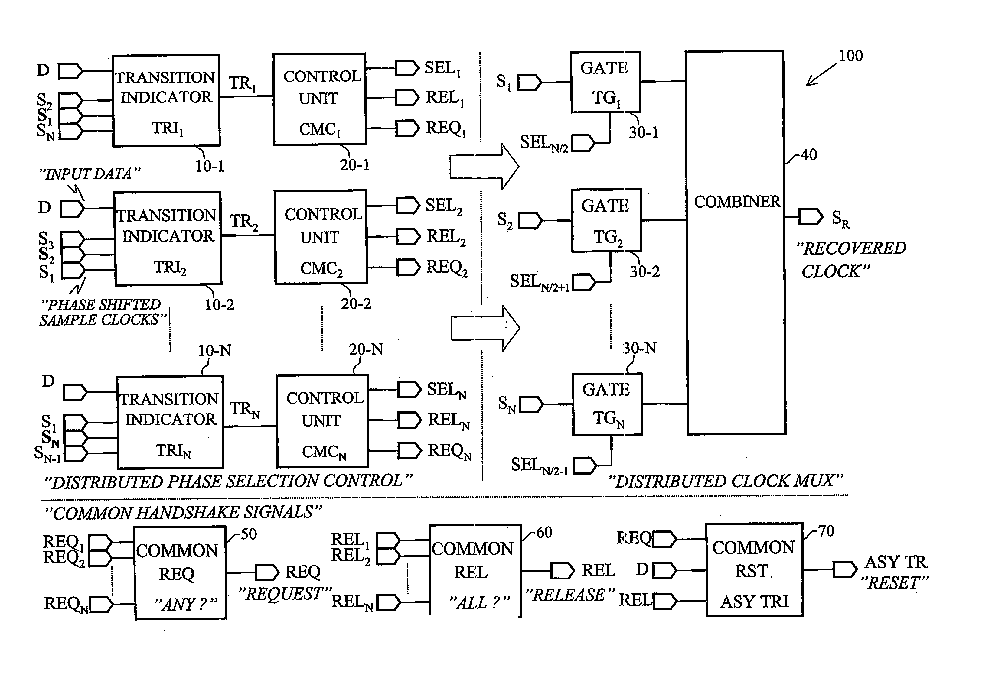
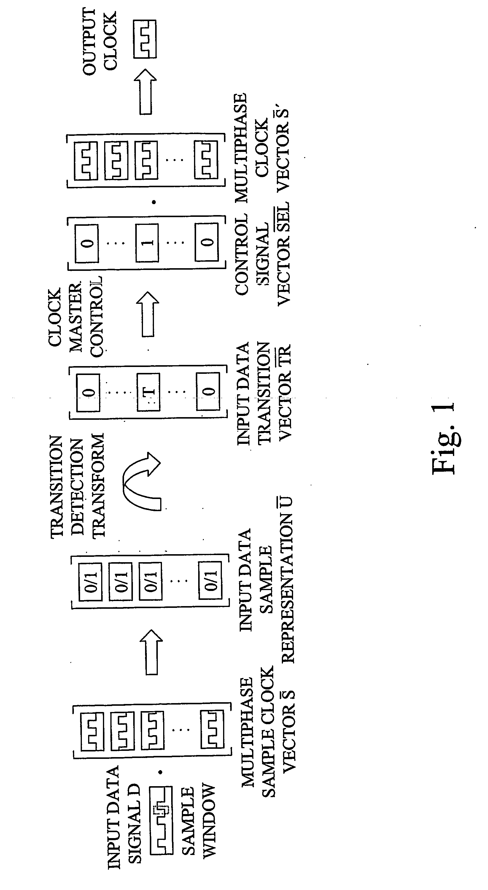
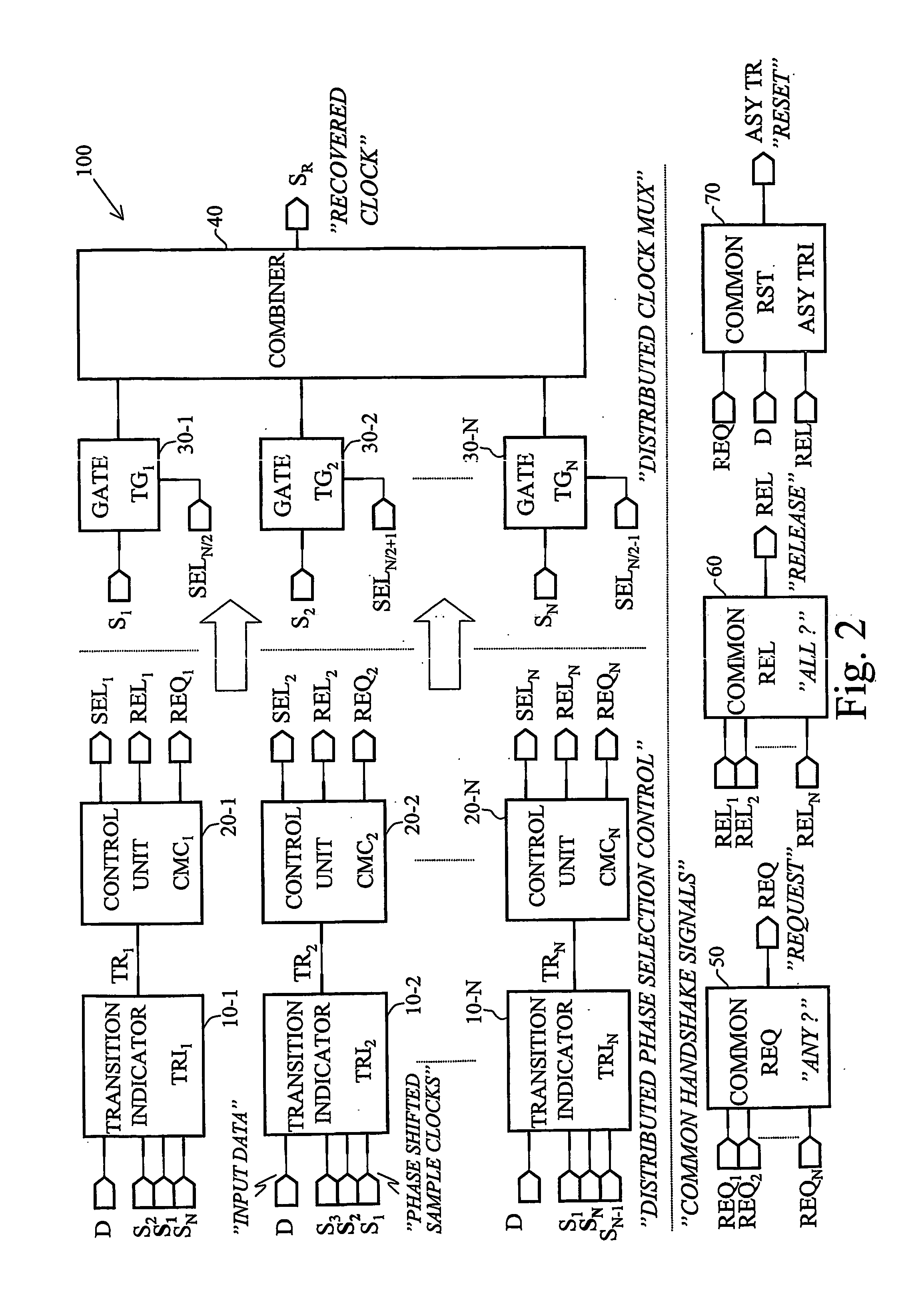
[0086] The invention represents a parallel and distributed approach to clock recovery. The clock recovery mechanism proposed by the invention operates based on multiple mutually phase shifted sample clock signals defining a set of orthogonal clock phases. Using the mathematical concepts of vectors and orthogonal systems in linear spaces, a vector-based notation is introduced to fully disclose the parallelism in the clock recovery algorithm. With reference to FIG. 1, the mutually phase shifted clock signals, forming a multiphase sample clock vector ( S), are employed for sampling an input data signal ...


PUM


Abstract

The invention represents a parallel and distributed approach to clock recovery based on multiple mutually phase shifted sample clock signals (åS) defining a set of orthogonal clock phases. The phase shifted clock signals are used for obtaining an input data sample representation (åU). Input data transition detection is accomplished by determining, for each one of the above clock phases, whether input data samples within a detection window associated with the respective clock phase include an input data transition vector (I). A corresponding clock selection control signal vector (I) is generated based on the input data transition vector (I) to determine a clock selection master. In order to dynamically extract an output clock signal, to control signal vector (I) is then logically combined with a representation (åS′), preferably a rotated version, of the sample clock vector (åS).

Description

TECHNICAL FIELD OF THE INVENTION [0001] The present invention generally relates to communication systems and digital clock recovery in such systems. BACKGROUND OF THE INVENTION [0002] High-speed digital communication channels or links often employ implicit synchronization with the source clock embedded in the transferred data. To interpret the input data correctly in another synchronous system or clock domain the source clock must first be recovered from the often sparse data transitions occurring in an irregular pattern. A fundamental object for any clock recovery mechanism is to extract timing information from an incoming data stream without the explicit knowledge of the source clock, hence the label embedded clock is often used to state that no explicit clock accompanies the input data. [0003] A clock signal is merely a regular data pattern alternating between marks and zeros (0101 . . . ). In general, a non-coded data stream contains significantly less synchronization informatio...

Claims


Application Information

Patent Timeline
Patent Type & Authority Applications(United States)
IPC IPC(8): H04L27/00H03L7/081H03L7/099H04L7/033
CPCH03L7/0812H04L7/0338H03L7/0995
Inventor FREDRIKSSON, JESPER JONAS
Owner TELEFON AB LM ERICSSON (PUBL)
Why Eureka
Try Eureka