Electrically variable transmission

a transmission and electric variable technology, applied in the field of transmissions, can solve the problems of limiting the manufacturing process that may be employed, and achieve the effect of superior cooling of the stator windings

Active Publication Date: 2008-07-22
ALLISON TRANSMISSION INC
View PDF22 Cites 48 Cited by
  • Summary
  • Abstract
  • Description
  • Claims
  • Application Information

AI Technical Summary

Benefits of technology

[0004]An electrically variable transmission is provided. The transmission includes a transmission housing defining a generally cylindrical cavity. The transmission also includes an electric motor located within the cavity. The electric motor includes a generally ring-shaped stator and a rotor. The transmission also includes a member having a generally cylindrical portion that circumscribes at least a portion of the stator. The member and the housing define an annular coolant flowpath therebetween, and the member includes a plurality of holes formed therein so that coolant in the annular flowpath flows radially inward toward the stator windings to provide a concentric radial spray feature. Concentric radial spray of coolant provides superior cooling of the stator windings compared to other methods available in the prior art, and therefore enables the motor to be smaller compared to the prior art.
[0005]In a preferred embodiment, the stator is mounted to the member rather than the housing, thus enabling larger manufacturing tolerances for the housing. The member thus enables the housing to be formed using manufacturing processes, such as die casting, suitable for high-volume production.
[0006]In a preferred embodiment, the transmission includes two motors mounted to the member to form a preassembled module for simplified assembly. The module enables insertion of the motors into the housing from one direction, and allows both of the stators, speed sensors, and wiring to be subassembled and tested prior to insertion into the housing. The module also provides ease of replacement during transmission servicing. The preassembled module enables a reduced transmission diameter compared to the prior art because the module, including both motors, may be fastened to the housing at the forward end and not at the rearward end, thus eliminating the rearward split-line.

Problems solved by technology

Thus, manufacturing tolerances for components, such as the housing, that interface with the motors are typically small and, accordingly, limit the manufacturing processes that may be employed.

Method used


Image

  • Electrically variable transmission
  • Electrically variable transmission
  • Electrically variable transmission

Examples


Embodiment Construction

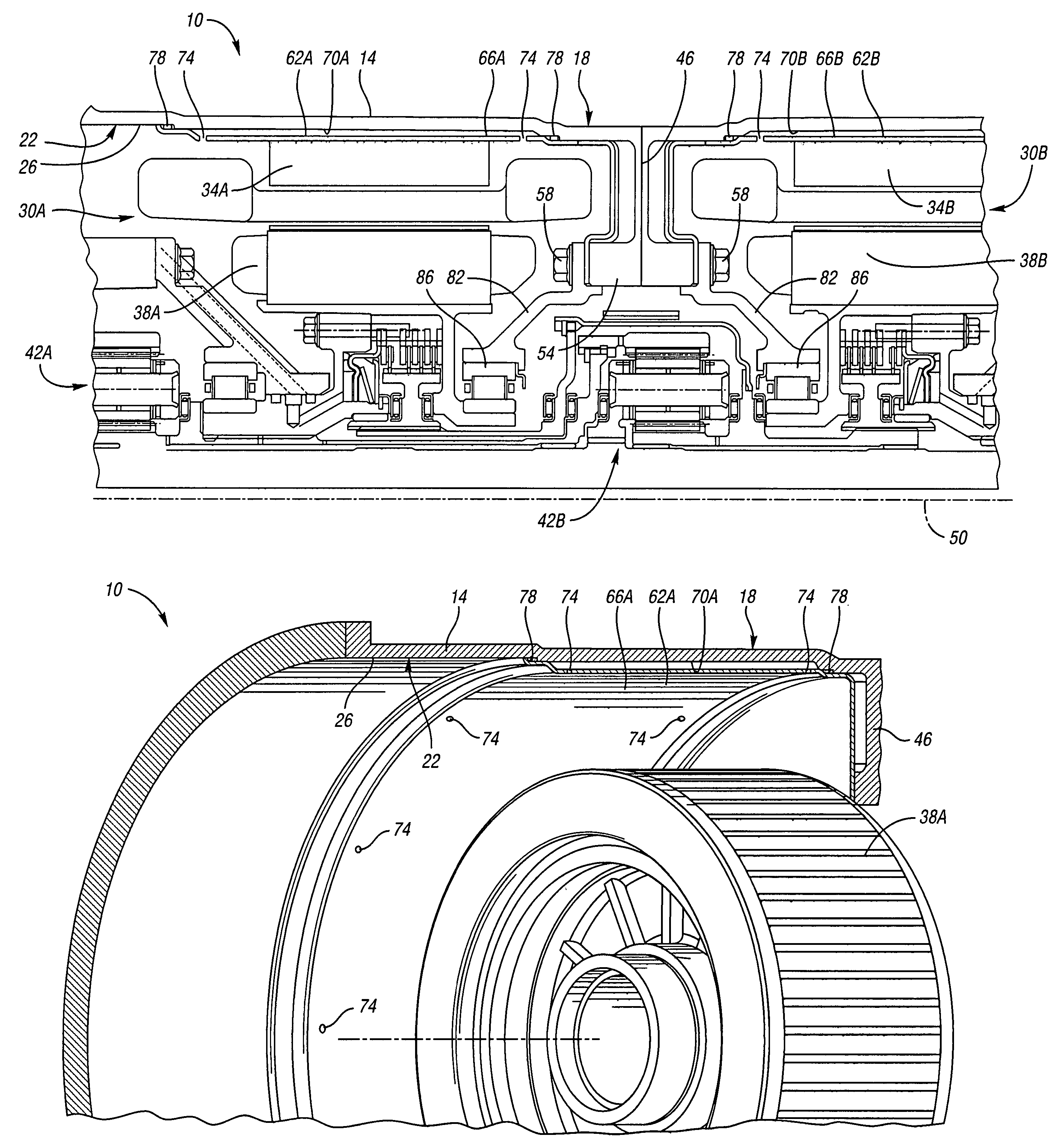
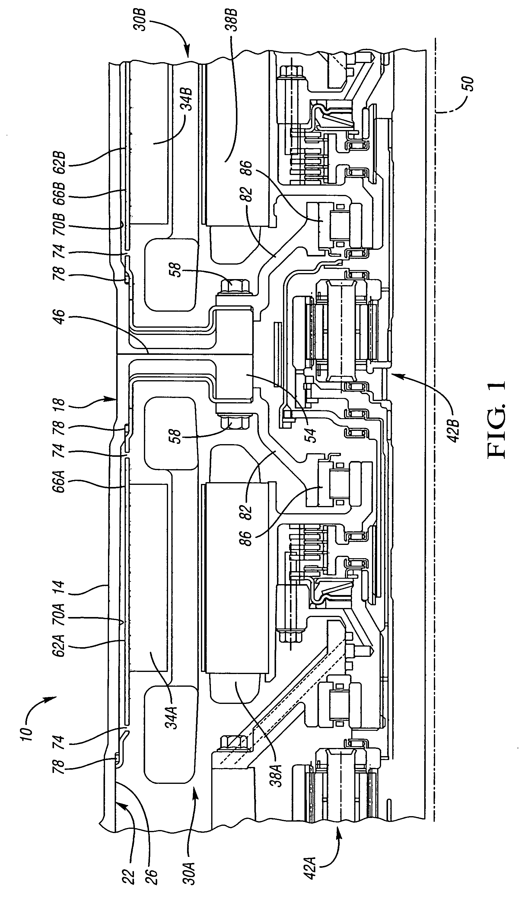
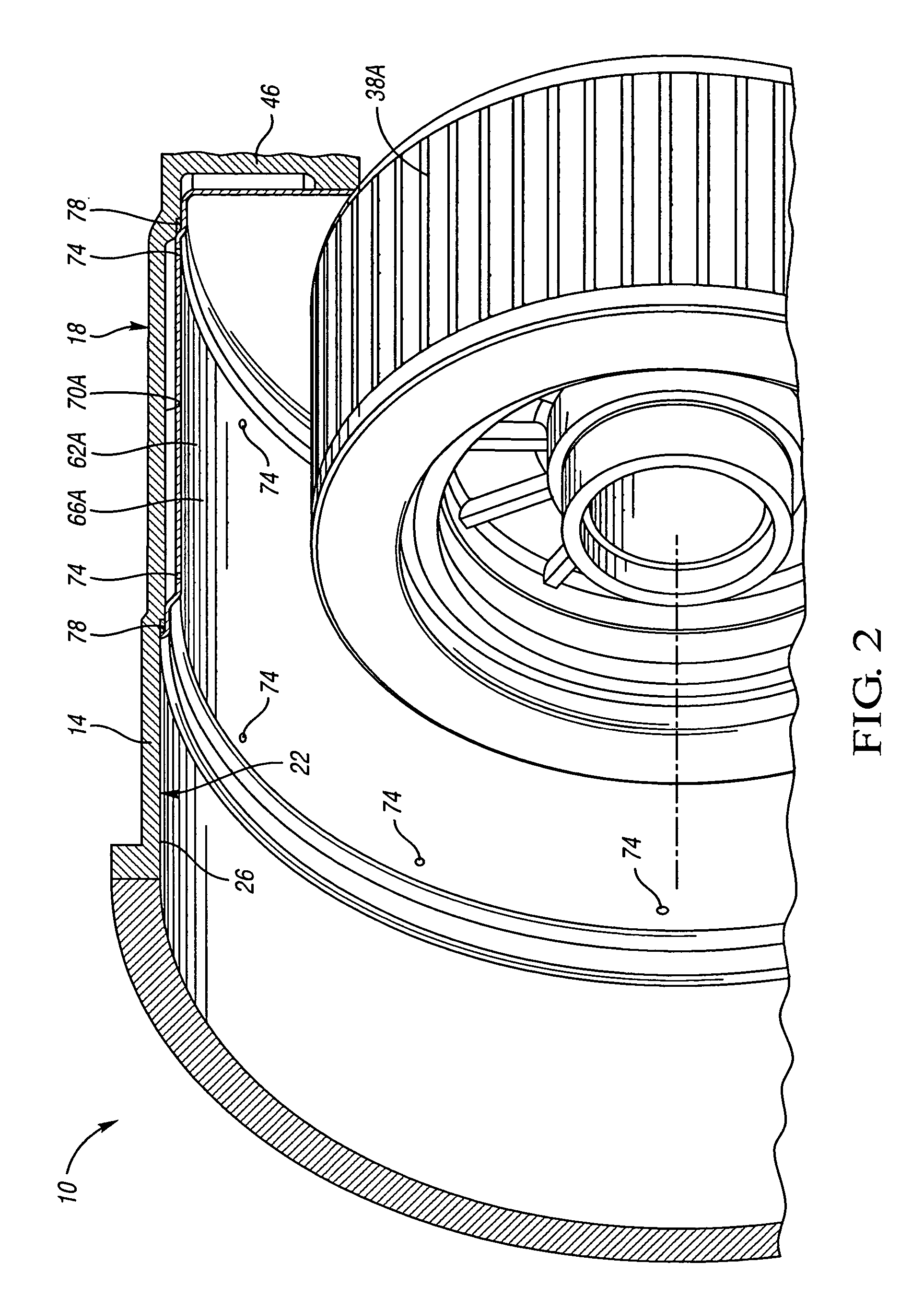
[0014]Referring to FIG. 1, a portion of an electrically variable transmission 10 is schematically depicted. Exemplary electrically variable transmissions are described in U.S. Pat. No. 5,558,595, issued Sep. 24, 1996 to Schmidt et al; U.S. Pat. No. 5,931,757, issued Aug. 3, 1999 to Schmidt; U.S. Pat. No. 6,478,705, issued Nov. 12, 2002 to Holmes et al; and U.S. Pat. No. 6,527,658, issued Mar. 4, 2003 to Holmes et al, each of which is hereby incorporated by reference in its entirety. The transmission 10 includes a housing 14 that defines the exterior surface 18 of the transmission. The housing 14 includes an inner surface 22 that defines a generally cylindrical cavity 26.

[0015]The transmission 10 also includes a first electric motor / generator 30A and a second electric motor / generator 30B. Each electric motor generator 30A, 30B includes a generally ring-shaped stator 34A, 34B fixed with respect to the housing 14, and a rotor 38A, 38B. The motors 30A, 30B are coaxially aligned with an ...


PUM


Abstract

A transmission includes a housing, an electric motor having a stator within the housing, and a member including a generally cylindrical portion that circumscribes at least part of the stator. The member cooperates with the housing to form an annular coolant flowpath therebetween, and the member includes a plurality of holes to provide radial inflow of coolant from the flowpath to the stator to provide significantly improved motor cooling compared to the prior art.

Description

TECHNICAL FIELD[0001]This invention relates to transmissions that include at least one electric motor, a housing, and a member that at least partially circumscribes the motor and cooperates with the housing to form an annular flowpath.BACKGROUND OF THE INVENTION[0002]Electrically variable transmissions, such as those described in U.S. Pat. No. 5,931,757, employ two electric motors mounted inside a transmission housing. The electric motors are coaxially oriented with an input shaft, an output shaft, and two planetary gearsets. Each motor is operatively connected to a member of one of the planetary gearsets to provide a range or mode of transmission operation characterized by a continuously variable speed ratio between the input shaft and the output shaft.[0003]The electric motors in electrically variable transmissions must have very precise location, low sensitivity of location to thermal events, and very uniform coolant flow. Thus, manufacturing tolerances for components, such as th...

Claims


Application Information

Patent Timeline
Patent Type & Authority Patents(United States)
IPC IPC(8): H02K9/00B60K1/02B60K11/02
CPCB60K6/365B60K6/405B60K6/48B60K1/02Y02T10/6221B60K2001/003F16H2037/106Y02T10/62
Inventor KLEMEN, DONALDEL-ANTABLY, AHMED M.SCHMIDT, MICHAEL R.
Owner ALLISON TRANSMISSION INC
Why Eureka
Try Eureka