Energy storage type feeder voltage compensation apparatus and method of controlling feeder voltage

a feeder voltage and compensation apparatus technology, applied in the direction of dynamo-electric converter control, secondary cell servicing/maintenance, toy trackways, etc., can solve the problems of lowering the availability of devices and electric rolling stock becoming uncomfortable to ride, so as to reduce the internal resistance of secondary batteries and reduce the loss of charging and discharging , the effect of increasing charging and discharging power

Active Publication Date: 2008-07-22
HITACHI IND PROD LTD
View PDF2 Cites 52 Cited by
  • Summary
  • Abstract
  • Description
  • Claims
  • Application Information

AI Technical Summary

Benefits of technology

[0007]An object of the present invention is to provide an energy storage type feeder voltage compensation apparatus and a method of controlling the feeder voltage, that are capable of ensuring chargeable and dischargeable power that is demanded from a secondary battery as a feeder voltage compensation apparatus, even at a low temperature state, and improving the availability of the apparatus as a whole.
[0012]In a preferred mode for carrying out the present invention, it is possible to lower the internal resistance of the secondary battery and decrease the charging and discharging loss, by restoring the temperature of the secondary battery that has fallen to a predetermined temperature.
[0013]In a preferred mode for carrying out the present invention, it is possible to increase the charging and discharging power and improve the availability of the voltage compensation apparatus as a whole.

Problems solved by technology

As a result, not only the electric rolling stock becomes uncomfortable to ride in, but also the power saving in the feeder system is aggravated.
4-7, however, the internal resistance value of the secondary battery becomes large at low temperatures, and chargeable and dischargeable power is restricted, resulting in a problem of a lowered availability of the device.

Method used


Image

  • Energy storage type feeder voltage compensation apparatus and method of controlling feeder voltage
  • Energy storage type feeder voltage compensation apparatus and method of controlling feeder voltage
  • Energy storage type feeder voltage compensation apparatus and method of controlling feeder voltage

Examples


first embodiment

[0026]A first embodiment of the present invention will now be described with reference to FIGS. 1 to 5.

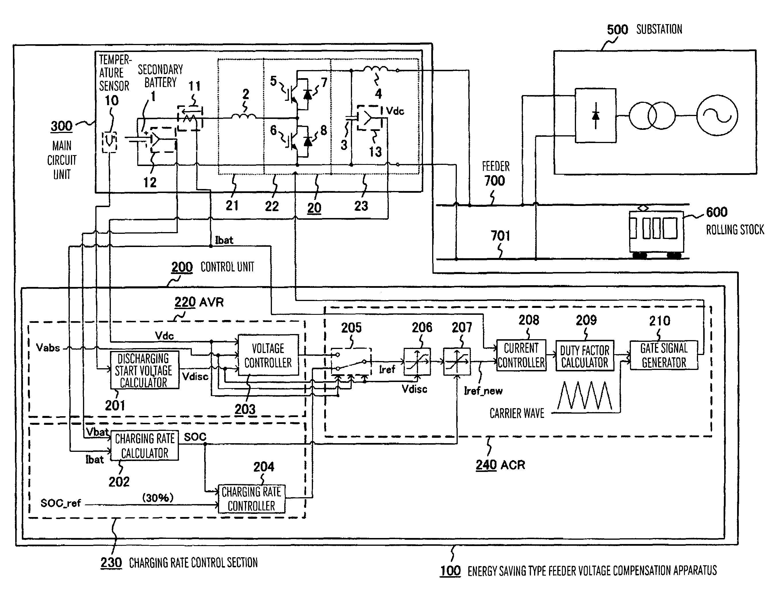
[0027]FIG. 1 is a general configuration diagram of an energy type feeder voltage compensation apparatus according to a first embodiment of the present invention. An energy saving type feeder voltage compensation apparatus (hereafter referred to simply as voltage compensation apparatus) 100, a substation 500, an electric rolling stock 600, a feeder 700, and rails 701 are shown. The voltage compensation apparatus 100 is connected in parallel to the substation 500 and the rolling stock 600 via the feeder 700 and the rails 701. The voltage compensation apparatus 100 includes a main circuit unit 300 and a control unit 200. First, the main circuit unit 300 will now be described.

[0028]In the main circuit unit 300, a secondary battery 1 is connected to the feeder 700 and the rails 701 via a power converter 20. In the present embodiment, the power converter 20 is formed by interposing a swi...

second embodiment

[0055]A second embodiment of the present invention will now be described with reference to FIGS. 6 and 7.

[0056]FIG. 6 is a general configuration diagram of an energy saving type feeder voltage compensation apparatus according to the second embodiment of the present invention. The present embodiment differs from the first embodiment in that control for raising the charging rate is previously exercised when the temperature of the secondary battery has become low. After the charging rate has become high, the discharging start voltage Vdisc is altered to the second discharging start voltage Vdisc2, which is higher than the no-load output voltage Vdc0 of the substation in the same way as the first embodiment. As a result, it is possible to increase the quantity of power that can be discharged, before the discharging running. Therefore, a greater temperature rise at the time of discharging running is expected.

[0057]Hereafter, the same function units as those shown in FIG. 1 are denoted by...

third embodiment

[0063]A third embodiment of the present invention will now be described with reference to FIG. 8.

[0064]FIG. 8 is a general configuration diagram of an energy saving type feeder voltage compensation apparatus according to the third embodiment of the present invention. The present embodiment differs from the first embodiment in that there are a plurality of energy saving type feeder voltage compensation apparatuses each including a secondary battery and a power converter. A voltage administrator for exercising general control over the energy saving type feeder voltage compensation apparatuses is provided. The voltage administrator outputs a charging start voltage and a discharging start voltage. As a result, charging and discharging of the secondary battery become possible even if the substation and the rolling stock are not connected.

[0065]Hereafter, only points that are different from the preceding embodiments will be described. In FIG. 8, the same function units as those shown in F...


PUM


Abstract

An energy saving type feeder voltage compensation apparatus improved in availability at low temperatures, wherein when a secondary battery is lower in temperature than a predetermined value, an output voltage output to a feeder side is made equal to or higher than a no-load output voltage of a substation connected in parallel. Power is supplied to a power running rolling stock preferentially from the secondary battery. The heating value of the secondary battery is increased and the battery temperature is raised by this discharging, whereby internal resistance of the secondary battery is lowered, and the charging and discharging loss is suppressed, and the efficiency and availability of the energy saving type feeder voltage compensation apparatus as a whole are improved.

Description

BACKGROUND OF THE INVENTION[0001]The present invention relates to an energy storage type feeder voltage compensation apparatus and a method of controlling feeder voltage in which a secondary battery is connected to a feeder of an electric railroad via a power converter to absorb surplus power on the feeder and supply power from a secondary battery in response to power demand from power running rolling stocks.[0002]In recent years, in a feeder system for supplying power from a substation to an electric rolling stock, the electric rolling stock utilizes regenerative brake with the object of power saving. This regenerative brake converts kinetic energy of the electric rolling stock to electric energy by using an inverter mounted on the electric rolling stock, regenerates the electric energy to the feeder, and decelerates the electric rolling stock. The electric energy generated by the regenerative brake is consumed as power running energy of other electric rolling stocks. As a result, ...

Claims


Application Information

Patent Timeline
Patent Type & Authority Patents(United States)
IPC IPC(8): H02J7/04H02J7/16
CPCB60L3/0046B60L11/1862B60L11/1864B60L11/1875H01M10/44H01M10/486H02J7/34B60L2240/545B60L2240/547B60L2200/26Y02T10/7005Y02T10/7061Y02T10/7044B60L2240/549B60L58/13B60L58/21B60L58/27B60L58/14B60L58/15Y02T10/70Y02E60/10
Inventor ITO, TOMOMICHIKATO, TETSUYAIKIMI, TAKASHI
Owner HITACHI IND PROD LTD
Why Eureka
Try Eureka