Pulse domain encoder and filter circuits

Inactive Publication Date: 2008-07-22
HRL LAB
View PDF7 Cites 41 Cited by
  • Summary
  • Abstract
  • Description
  • Claims
  • Application Information

AI Technical Summary

Benefits of technology

[0021]The first one of the second order units may further include an input amplifier coupled to the first adder and responsive to the input signal. The input amplifier may be a 1-bit digital to analog converter. The filter circuit may implement a filter transfer function selected from a group consisting of Butterworth transfer function, Chebychev

Problems solved by technology

In the analog domain, a disadvantage of the conventional approach is that accuracy is severely limited by dynamic range of the analog components such as the feedback analog amplifiers.
Accuracy is limited by the analog components, such as operational amplifiers.
In the digital domain, the disadvantage of the conventional approach is that speed is limited by the performance of ADC conversion.
However the Hadamard circuit may not be used to solve differential equations.
Furthermore, the arithm

Method used


Image

  • Pulse domain encoder and filter circuits
  • Pulse domain encoder and filter circuits
  • Pulse domain encoder and filter circuits

Examples


Embodiment Construction

[0034]The following description pertains to ordinary differential equations and systems of coupled first order linear ordinary differential equations or higher order linear ordinary differential equations that may be written as systems of coupled first order linear ordinary differential equations.

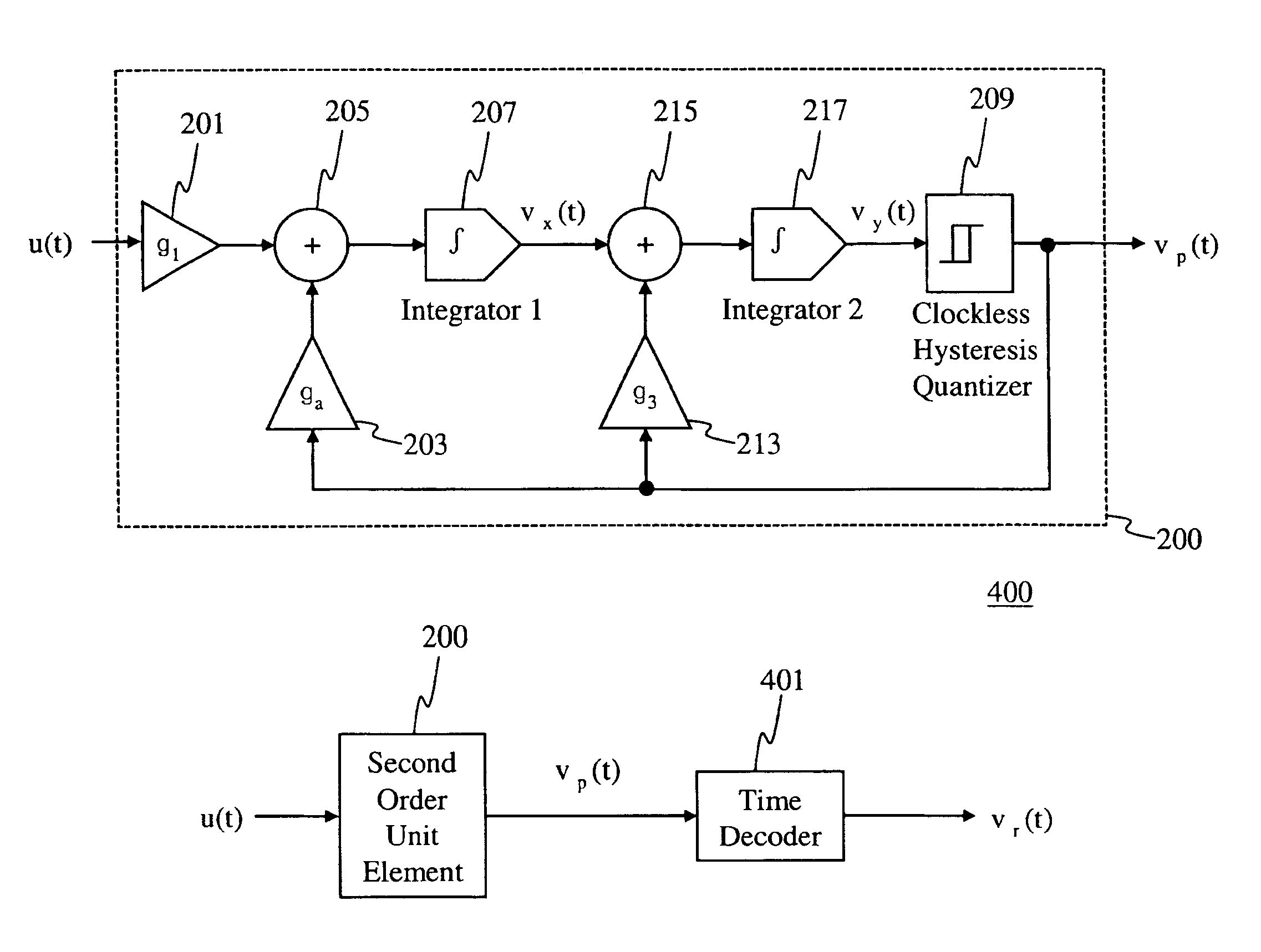
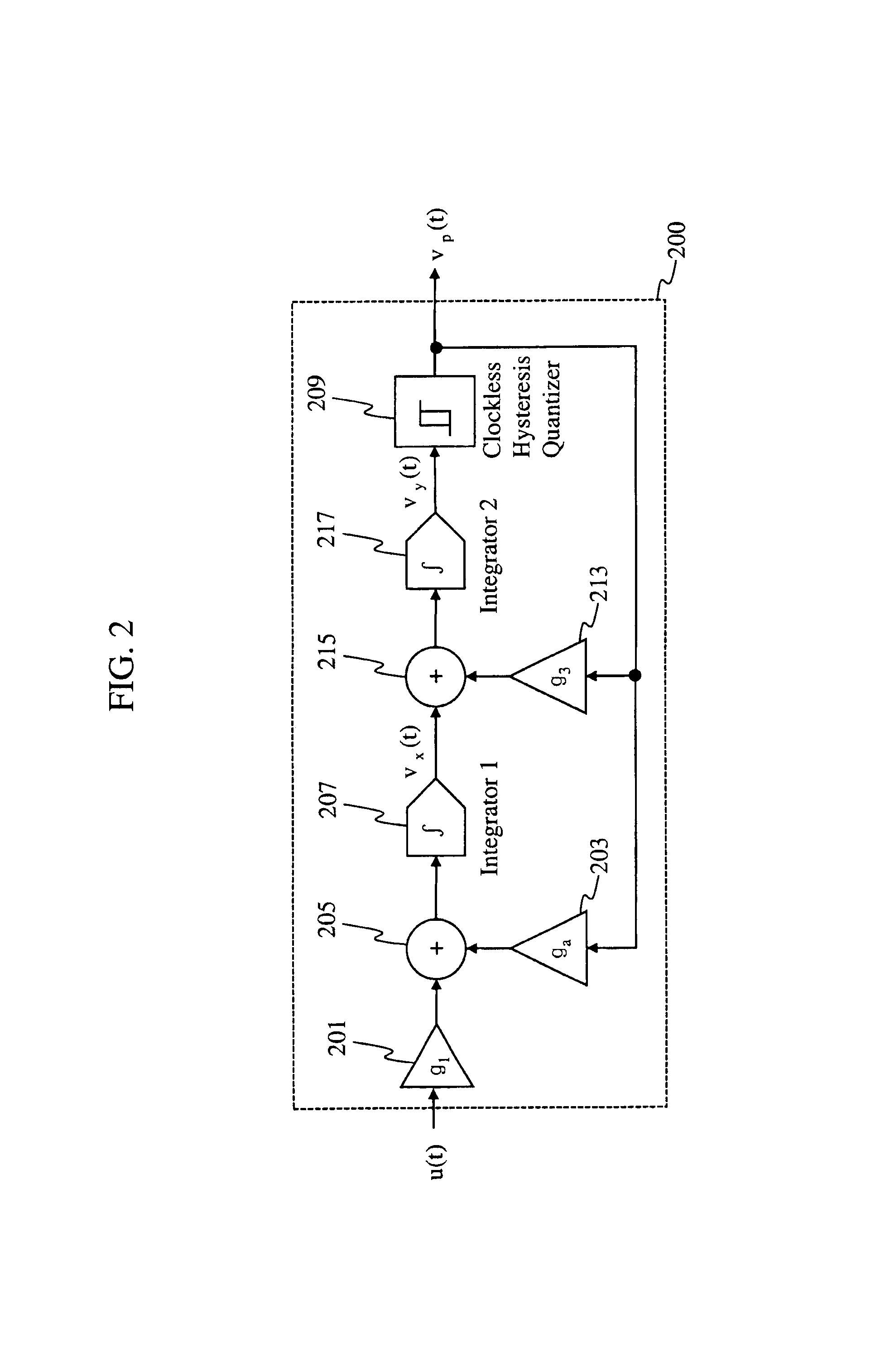
[0035]A first embodiment of the present invention provides a second order unit element circuit that is used to solve differential equations in the pulse domain. The circuit of the first embodiment is referred to as an encoder circuit. The encoder circuit computes an arbitrary first order differential equation with the solution projected in the time domain via a pulse output. The encoder circuit of the first embodiment does not require any analog feedback amplifier for performing this computation. All the internal feedback signals are pulse asynchronous signals being defined with just two amplitude levels. Simple 1-bit Digital to Analog Converters (DACs) are used in the feedback circuit. Gai...


PUM


Abstract

A pulse circuit to solve a system of differential equations in the pulse domain based on analog or inputs or time-encoded pulse inputs. Intrinsically linear 1-bit digital to analog converters are used as feedback elements within circuits implementing solutions to a differential equation or to a system of differential equations. The circuits may be used to implement filters. While the input to the circuit may be an analog signal, the internal signals of the circuit are time-encoded current or voltage pulses. Output of the circuit is a time-encoded pulse or a series of time-encoded pulses from which an analog output may be recovered by time decoding.

Description

BACKGROUND OF THE INVENTION[0001]a) Field of the Invention[0002]The present invention relates generally to the field of analog encoding and filtering and more particularly to solving systems of differential equations by encoder and filter circuits using time encoding and pulse domain signals.[0003]a) Description of Related Art[0004]Conventionally, differential equations could be solved in the (1) original analog domain via analog amplifiers or in the (2) digital domain after an Analog to Digital Converter (ADC) digitization. In the analog domain, a disadvantage of the conventional approach is that accuracy is severely limited by dynamic range of the analog components such as the feedback analog amplifiers. Conventional circuits for solving differential equations in the analog domain are based on analog computation where the information is encoded in the amplitude of voltages or current signals. Accuracy is limited by the analog components, such as operational amplifiers. In the digi...

Claims


Application Information

Patent Timeline
IPC IPC(8): H03M3/00
CPCH03M3/496H03M3/43H03M3/454
Inventor CRUZ-ALBRECHT, JOSE M.PETRE, PETER
Owner HRL LAB
Why Eureka
Try Eureka