Asymmetric ethernet network data transfer system and method

a technology of ethernet network and data transfer system, applied in the field of network data transfer system, can solve the problems of data transfer congestion, unused bandwidth, and unused bandwidth, and achieve the effect of avoiding bandwidth unused, reducing bandwidth unused, and reducing bandwidth unused

Active Publication Date: 2008-07-22
VIA TECH INC
View PDF1 Cites 19 Cited by
  • Summary
  • Abstract
  • Description
  • Claims
  • Application Information

AI Technical Summary

Benefits of technology

[0006]The present invention is directed towards the above-mentioned need. The present invention provides an asymmetric network data transfer system to solve the problem of impropriate bandwidth allocation caused by the symmetry feature of the Ethernet without substantially changing current network data transfer mechanism and equipment, and though which to correspond to both industrial and economic needs.
[0007]The present invention discloses an asymmetric Ethernet network data transfer system and method. The present invention utilizes a network interface card being capable of an automatic transfer mode switch to form an asymmetric data transfer system, and through which to modify the symmetry feature of the Ethernet and increase the transfer bandwidth. To avoid misunderstanding, in this text the word “bandwidth” will be separated by meaning by using “physical bandwidth” to refer to the max bearable data flow rate (the unit is bps: bit per second) of the transfer medium (which will be the network cable herein); and “transfer bandwidth” to refer to the bandwidth actually used during the data transfer process. The word “asymmetric” herein is in connection with the transfer bandwidth. The present invention only modifies some designs within the network interface card, all other current hardware and software used for network data transfer including the network cables need not change. For example, while the specification IEEE 802.3 is used in the network, the asymmetric character of the invention could be archived by modifying the program code Link_Control_[HCD]. Herein, the original concepts at least are “Speed: 10 / 100 / 1000; Duplex: Half / Full; FControl: Tx / Rx”, and the invention could be archived by adding the new configuration to be new concepts of the program code. Further, one thing should be noticed is that the network cable used must support two-way data transfer, i.e. the network cable must not have the direction feature. For example, the common copper twisted pair like Cat 5 is capable of two-way data transfer, while the optical fiber isn't. Accordingly, the present invention can be easily integrated into current network data transfer framework and can increase network data transfer efficiency with low extra construction cost, which corresponds to the industrial needs.
[0009]Through the function mentioned above, an asymmetric network data transfer system being capable of real-time adjustments in the ways the two network cables connected to the provided network interface card are used is formed. The asymmetric network data transfer system enables the present invention to improve data transfer efficiency of the Ethernet by real-time switches between symmetric and asymmetric data transfer mechanisms.

Problems solved by technology

Thus, the symmetry feature often causes congestion problems to data transfer in the transfer direction with insufficient bandwidth and leaves bandwidth unused in the transfer direction with transfer bandwidth more than needed.
Thus, while transferring data, the symmetry feature of the Ethernet often causes congestion problems to the data transfer in the transfer direction with insufficient bandwidth and leaves bandwidth unused in the transfer direction with transfer bandwidth more than needed.

Method used


Image

  • Asymmetric ethernet network data transfer system and method
  • Asymmetric ethernet network data transfer system and method
  • Asymmetric ethernet network data transfer system and method

Examples


first embodiment

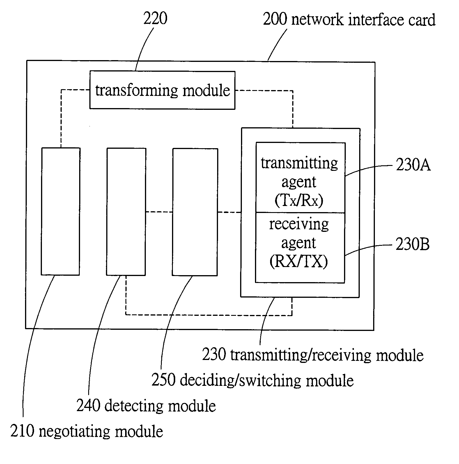
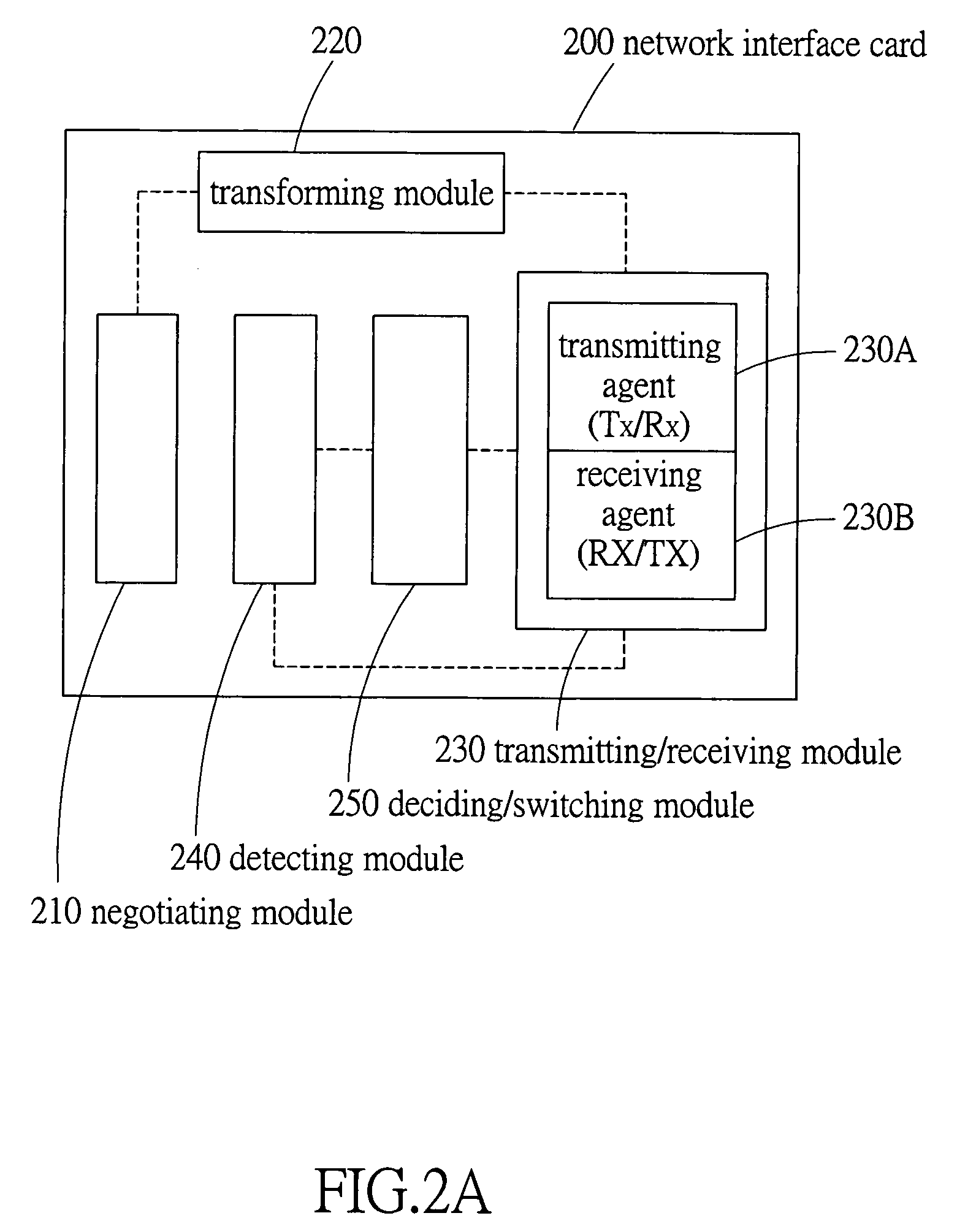
[0019]Reference is now made to FIG. 2A, in the present invention, a network interface card 200 being capable of the one-way / two-way network cable transfer mode switch is provided. The network interface card 200 comprises: a negotiating module 210 to negotiate with the target network apparatus for the packet format for data transfer; a transforming module 220 to perform the transformation between the digital data (usually used in the computer) and the packets (usually used in the network) according to the packet format agreed on; a detecting module 240 to detect the network condition (ex: the loading, speed and whether the network interface card of the target network apparatus being capable of the one-way / two-way network cable transfer mode switch); a deciding / switching module 250 to decide whether to perform the one-way / two-way network cable transfer mode switch according to the detecting result from the detecting module 240; and a transmitting / receiving module 230 wherein the trans...

second embodiment

[0025]Reference is now made to FIG. 3A, which is a block diagram illustrating a network data transfer system 300 in accordance with a The network data transfer system 300 comprises numerous network apparatuses 310 / 320, wherein each of the network apparatuses 310 / 320 can be a personal computer, a server, a switch or a hub. Detailed descriptions of the network apparatuses 310 / 320 will not be given herein since they are well-known elements. The network apparatus 310 comprise a network interface card 311 (which is new and not a well-known element) being capable of the one-way / two-way network cable transfer mode switch; the network interface card 311 further comprises a transmitting agent 311A and a receiving agent 311B. The network apparatus 320 comprise a network interface card 321 being capable of the one-way / two-way network cable transfer mode switch; the network interface card 321 further comprises a transmitting agent 321A and a receiving agent 321B. The transmitting agent 311A is...

third embodiment

[0028]Reference is now made to FIG. 3B, which is a block diagram illustrating a network data transfer system 350 in accordance with the present invention. The network data transfer system 350 comprises numerous network apparatuses 360 / 370, wherein each of the network apparatuses 360 / 370 can be a personal computer, a server, a switch or a hub. Detailed descriptions of the network apparatuses 360 / 370 will not be given herein since they are well-known elements. The network apparatus 360 comprises a network interface card 361 (which is new and not a well-known element) being capable of the one-way / two-way network cable transfer mode switch; the network interface card 361 further comprises a transmitting agent 361A and a receiving agent 361B. The network apparatus 370 comprises a network interface card 371 being capable of the one-way / two-way network cable transfer mode switch; the network interface card 371 further comprises a transmitting agent 371A and a receiving agent 371B. The tran...


PUM


Abstract

The present invention provides an asymmetric Ethernet network data transfer system and method. The present invention utilizes a network interface card being capable of an automatic transfer mode switch to form an asymmetric network data transfer system, and through which to modify the symmetry feature of the Ethernet and increase the transfer bandwidth.

Description

BACKGROUND OF THE INVENTION[0001]1. Field of the Invention[0002]The present invention is related to a network data transfer system, and more particularly, to an asymmetric Ethernet network data transfer system.[0003]2. Description of the Prior Art[0004]With the quick improvements in technology, the network has become an indispensable communication medium in modern society. Of all the networks, the local area network is the most popular one due to the well-developed and inexpensive devices of it. The Ethernet is a common local-area-network technique. It consists of an Ethernet card and other network connection devices. The conventional Ethernet has a symmetry feature in data transfer, which means that the bandwidths used in the downloading and uploading data transfer works are equal. However, usually the practical downloading and the practical uploading data transfer rates are different. Thus, the symmetry feature often causes congestion problems to data transfer in the transfer dire...

Claims


Application Information

Patent Timeline
Patent Type & Authority Patents(United States)
IPC IPC(8): H04L12/28H04L12/56
CPCH04L12/2801
Inventor HUANG, SCOTT
Owner VIA TECH INC
Why Eureka
Try Eureka