

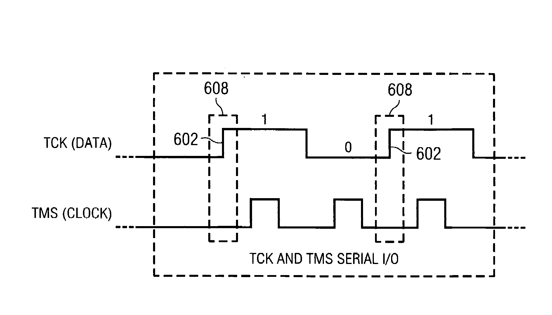
Serial data I/O on JTAG TCK with TMS clocking
a serial data and tms clocking technology, applied in logic circuit coupling/interface arrangement, generating/distributing signals, instruments, etc., can solve the problem of not optimizing the data communication bandwidth between a target tap domain and a controller b>320/b>
- Summary
- Abstract
- Description
- Claims
- Application Information
AI Technical Summary
Benefits of technology
Problems solved by technology
Method used
Image

Examples
Embodiment Construction
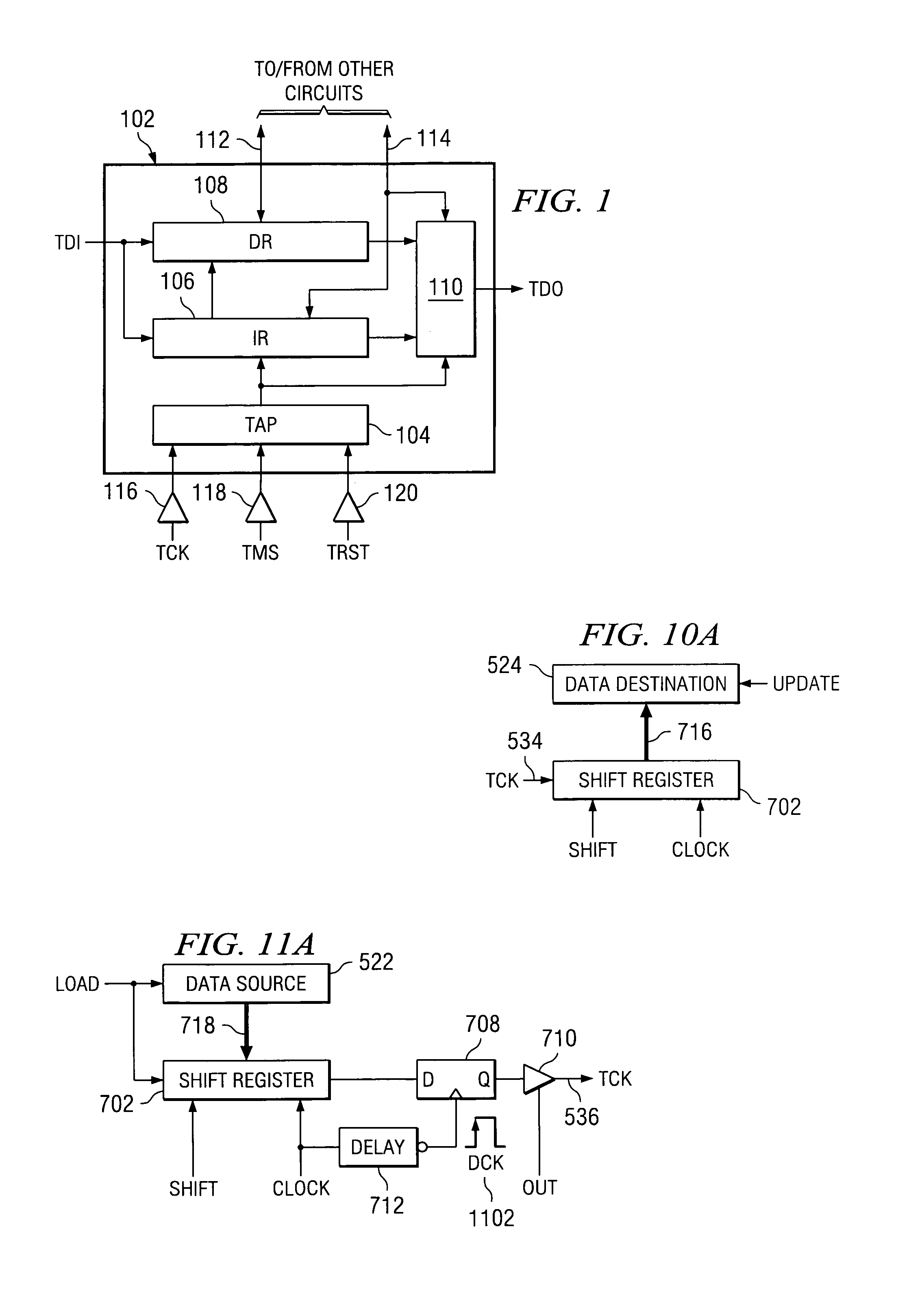
[0046]FIG. 4 illustrates a scan path system 402 of ICs / cores that include TAP domains plus additional I / O circuitry. The combination of the TAP domain and I / O circuitry is referred to as TAPIO 416. FIG. 4 is similar to FIG. 3 in regard to the way the TDI, TDO, TCK, TMS, and TRST signals are coupled between the TAPIOs 416 and controller 420. Controller 420 is different from controller 320 in that it has been improved according to the present disclosure to include the capability of communicating data to and from the TAPIOs 416 via the TMS and TCK connections. Controller 420 maintains the conventional capability of controller 320 to communicate to the TAP domains of the TAPIOs 416 using the standard IEEE 1149.1 serial protocol.
[0047]As seen in FIG. 4, the TCK connection between controller 420 and TAPIOs 416 is shown as a bidirectional signal path, as opposed to the unidirectional signal path of the TCK connection in FIG. 3. When a TAPIO 416 is selected for sending data to the controlle...
PUM
 Abstract
Description
Claims
Application Information