
Faucet structure

a faucet and structure technology, applied in the field of faucet structure, can solve the problems of increasing the burden on the washbasin, posing potential dangers to users in daily life, and difficult to assemble or dismantle, and achieve the effects of saving application, avoiding the risk of toxic metallic materials, and smooth transportation

Inactive Publication Date: 2008-07-29
CHANG KIM
View PDF5 Cites 24 Cited by
  • Summary
  • Abstract
  • Description
  • Claims
  • Application Information

AI Technical Summary

Benefits of technology

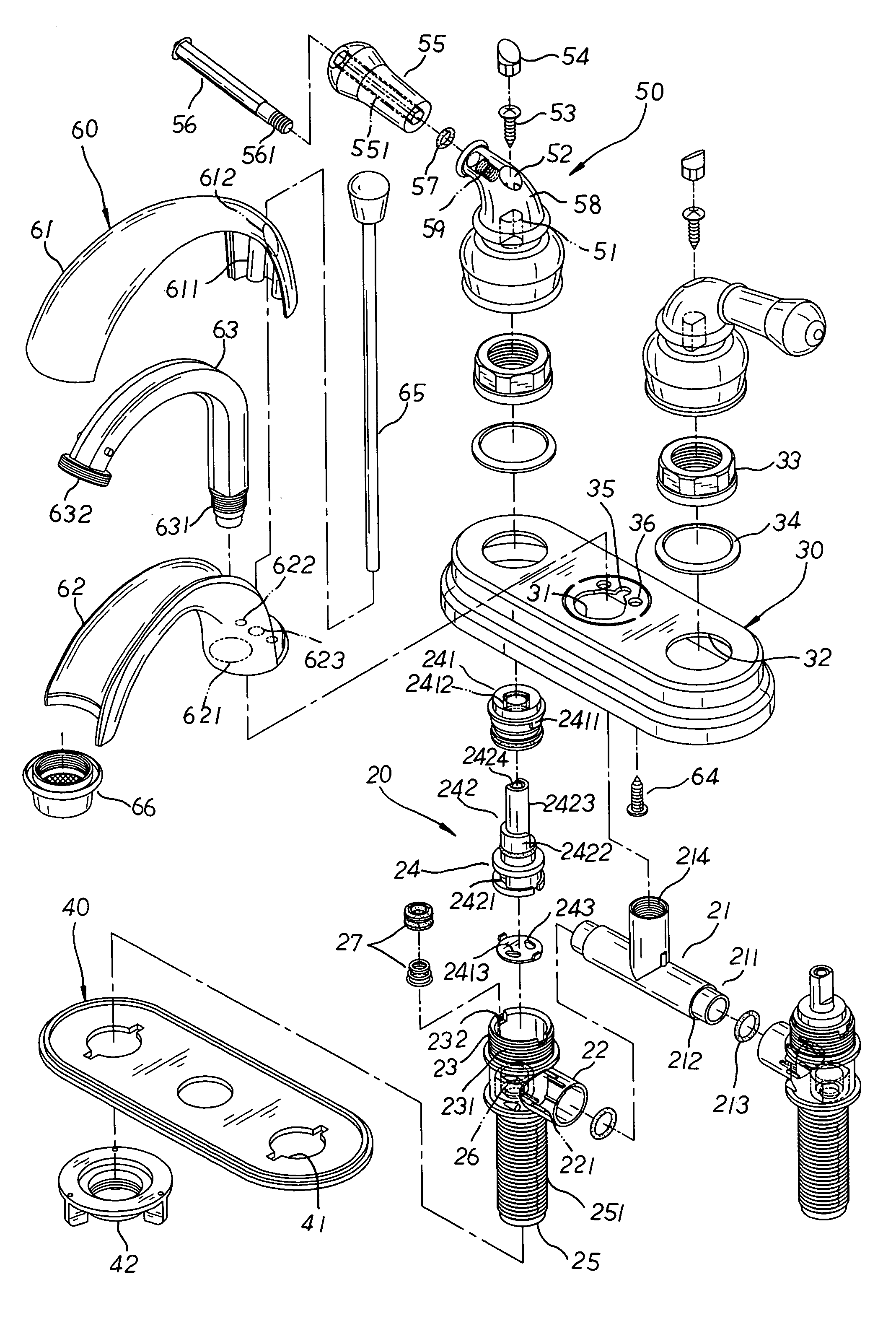
[0004]It is, therefore, the primary purpose of the present invention to provide a faucet structure wherein the faucet is molded of plastic material so that the assembly parts manufactured thereby can have smooth surfaces with fine and tightened pores defining thereon, avoiding the risk of toxic metallic material remained therein as well as facilitating smooth transportation of the water flow without the limescale deposited therein so as to achieve the state of clean and save application thereby.
[0005]It is, therefore, the second purpose of the present invention to provide a faucet structure wherein the faucet is molded of plastic material that can be freely processed and flexibly mixed in various colors without the complicated steps such as burnishing, polishing, and lacquering, reducing the cost of material and production to boost the economical efficiency thereby.
[0006]It is, therefore, the third purpose of the present invention to provide a faucet structure wherein the faucet has a connecting tube equipped with coupling ends at both sides and detachably mounted to a valve body to form a collapsible-type assembly so that a user can freely dismantle the valve body for cleaning or replacement, reducing the weight of the faucet on the washbasin for more durable use and augmenting the convenience and flexibility of the present invention in application.

Problems solved by technology

There are some drawbacks to the conventional faucet above.
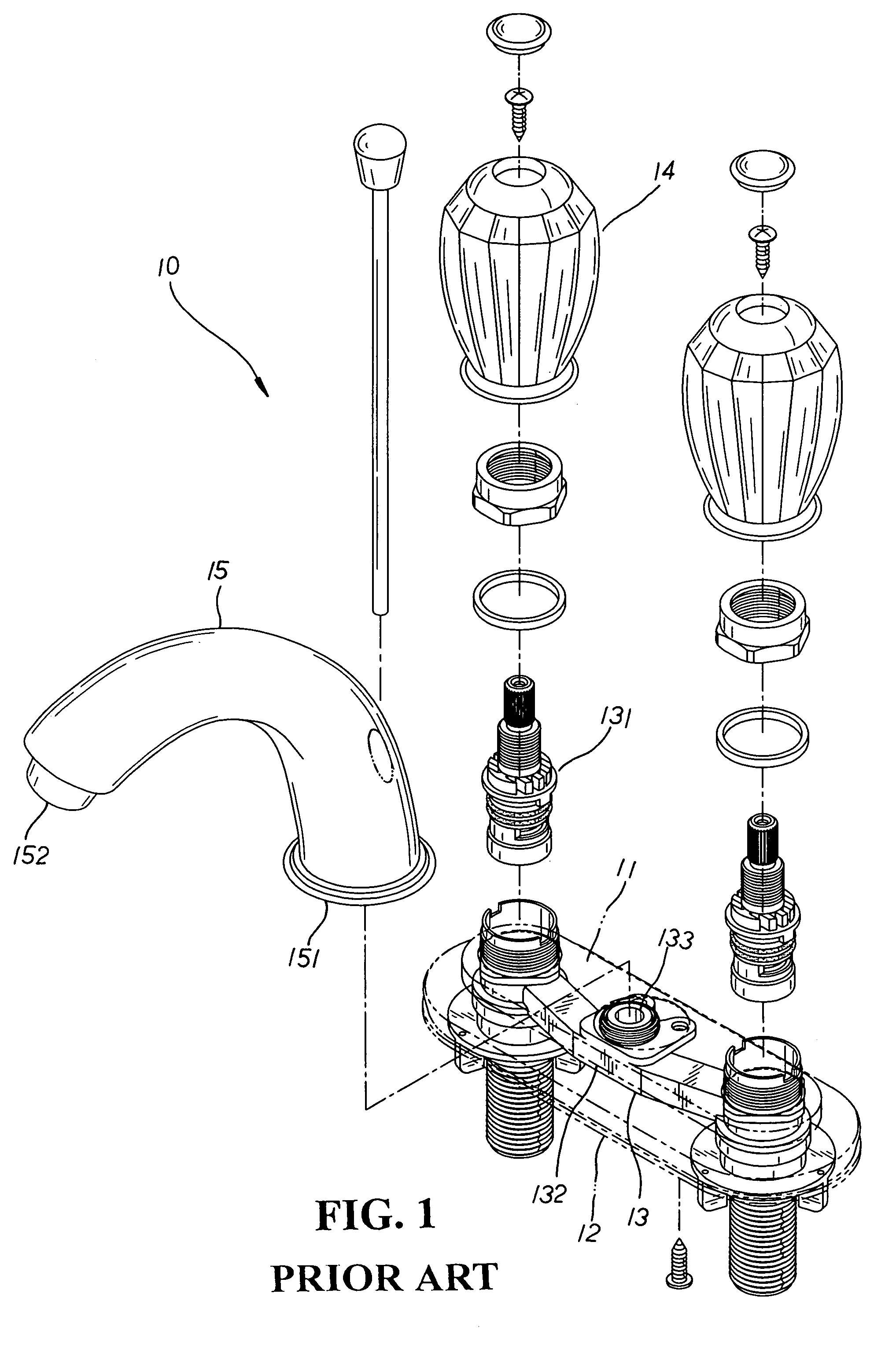
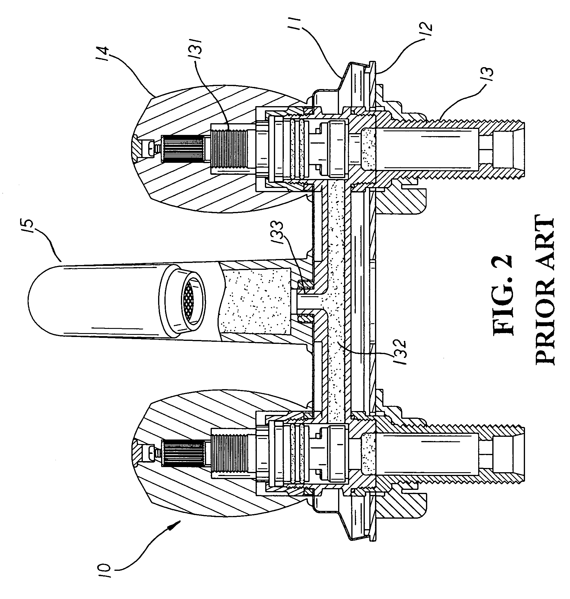
First, the faucet 10 is integrally molded, which not only makes it difficult to assemble or dismantle, but can increase the burden to a washbasin due to its heavy weight in application.
Second, the faucet 10 is made of metallic material, and the remains of toxic metallic material thereof tend to mix into the water flow, posing potential danger to users in daily life.
Third, the assembly parts of the control valve 131 thereof are numerous and complicated, which can increase the costs of material and processing as well as augmenting the difficulty of assembly and maintenance thereof.
Besides, the valve body 13 is fixedly mounted onto the faucet 10, which makes the replacement or maintenance of the faucet 10 rather difficult and time-consuming.

Method used


Image

  • Faucet structure
  • Faucet structure
  • Faucet structure

Examples


Embodiment Construction

[0017]Please refer to FIG. 4 showing an exploded perspective view of the present invention. The present invention relates to a faucet structure, comprising a faucet molded of high / low-temperature resistant plastic material and equipped with an H-shaped valve body 20 wherein a connecting tube 21 is detachably mounted to the middle section of the valve body 20. The connecting tube 21 has a pair of coupling ends 211 protruding at both end sides thereon, and each coupling end 211, having a stop surface 212 defining thereon for the mounting of a sealing ring 213 thereon, is joined to an outlet sleeve 22 disposed at both lateral sides of the valve body 20 respectively. The inner surface of the outlet sleeve 22 has multiple ribs 221 annularly arranged in spacing thereon so that the sealing ring 213 is precisely pressed by the stop surface 212 and restricted in position by the ribs 221 there-between. Besides, both ends of the outlet sleeve 22 are respectively joined to an accommodating tube...


PUM


Abstract

A faucet structure comprises a valve body having outlet sleeves, accommodating tubes, and inlet connecting pipes to be mounted between a panel equipped with a passage, bores, a clearance recess, and through holes, and a cover having a set of holes. The middle section of the valve body is disposed a connecting tube having a set of coupling ends each joined to one outlet sleeve, and an assembly section to fit to an outlet duct of a water supply seat. The valve body also has a water-flow control valve received into the accommodating tube to match to a handle seat with a grip attached thereto. The water supply seat formed by a set of upper and lower housings assembled to each other to enclose the outlet duct therein is mounted to the middle section of the panel thereon. Therefore, the present invention can achieve easy and flexible assembly thereby.

Description

BACKGROUND OF THE INVENTION[0001]The present invention relates to a faucet structure wherein the faucet is molded of plastic material that can be freely processed and flexibly mixed in various colors without the complicated steps such as polishing, burnishing and lacquering, economically reducing the cost of material and production thereby. Besides, the faucet includes a valve body with a connecting tube detachably mounted thereto so that a user can easily assemble or dismantle the valve body as desired, facilitating the convenience and flexibility of the present invention in application.[0002]Please refer to FIG. 1 showing an exploded perspective view of a conventional faucet structure. A conventional faucet 10 includes a panel 11, a cover 12, and an integrally molded H-shaped valve body 13 that, having a control valve 131 received at both sides therein respectively, is mounted between the panel 11 and the cover 12 thereof. The middle section of the valve body 13 has a flow duct 13...

Claims


Application Information

Patent Timeline
Patent Type & Authority Patents(United States)
IPC IPC(8): F16K11/22
CPCE03C1/04F16K19/006F16K11/20F16K3/08Y10T137/6977Y10T137/87684Y10T137/9464
Inventor CHANG, KIM
Owner CHANG KIM
Learn More