Analytical furnace with predictive temperature control

a technology of predictive temperature control and analytical furnace, which is applied in the direction of crystal growth process, drying solid materials, drying machines, etc., can solve the problems of less than desirable performance accuracy and slow operation, and achieve faster and accurate analysis, prevent excessive overshooting of temperature, and analyze multiple samples quickly and accurately

Active Publication Date: 2008-07-29
LECO CORPORATION
View PDF15 Cites 15 Cited by
  • Summary
  • Abstract
  • Description
  • Claims
  • Application Information

AI Technical Summary

Benefits of technology

[0005]The system of the present invention provides an analytical furnace with a predictive temperature control. In one embodiment, a batch-type macro thermogravametric analyzer is provided which is capable of analyzing multiple samples rapidly and accurately by providing a predictive temperature control utilizing at least a pair of temperature sensors in the furnace. One sensor is mounted in fixed relationship in the furnace, and a second sensor is mounted within a crucible for training and tuning the temperature profile, such that the crucible temperature in which a sample is placed can be modeled and its response to the application of energy to the furnace in accordance with the furnace's dynamic thermal characteristics known, predictable and controllable. By employing a pair of temperature sensors, with one being located in a crucible during the modeling of the temperature profile within the crucible, the furnace can be controlled to provide a faster, more accurate analysis and prevent excessive overshooting of temperature as desired temperature plateaus are more quickly approached.

Problems solved by technology

Prior art analyzers performing sample analyses and analyzers performing multiple sample thermogravametric analyses typically use a furnace having a single temperature sensor, which, although providing adequate analysis information, can suffer from slow operation and less than desirable accuracy in performance.

Method used


Image

  • Analytical furnace with predictive temperature control
  • Analytical furnace with predictive temperature control
  • Analytical furnace with predictive temperature control

Examples


Embodiment Construction

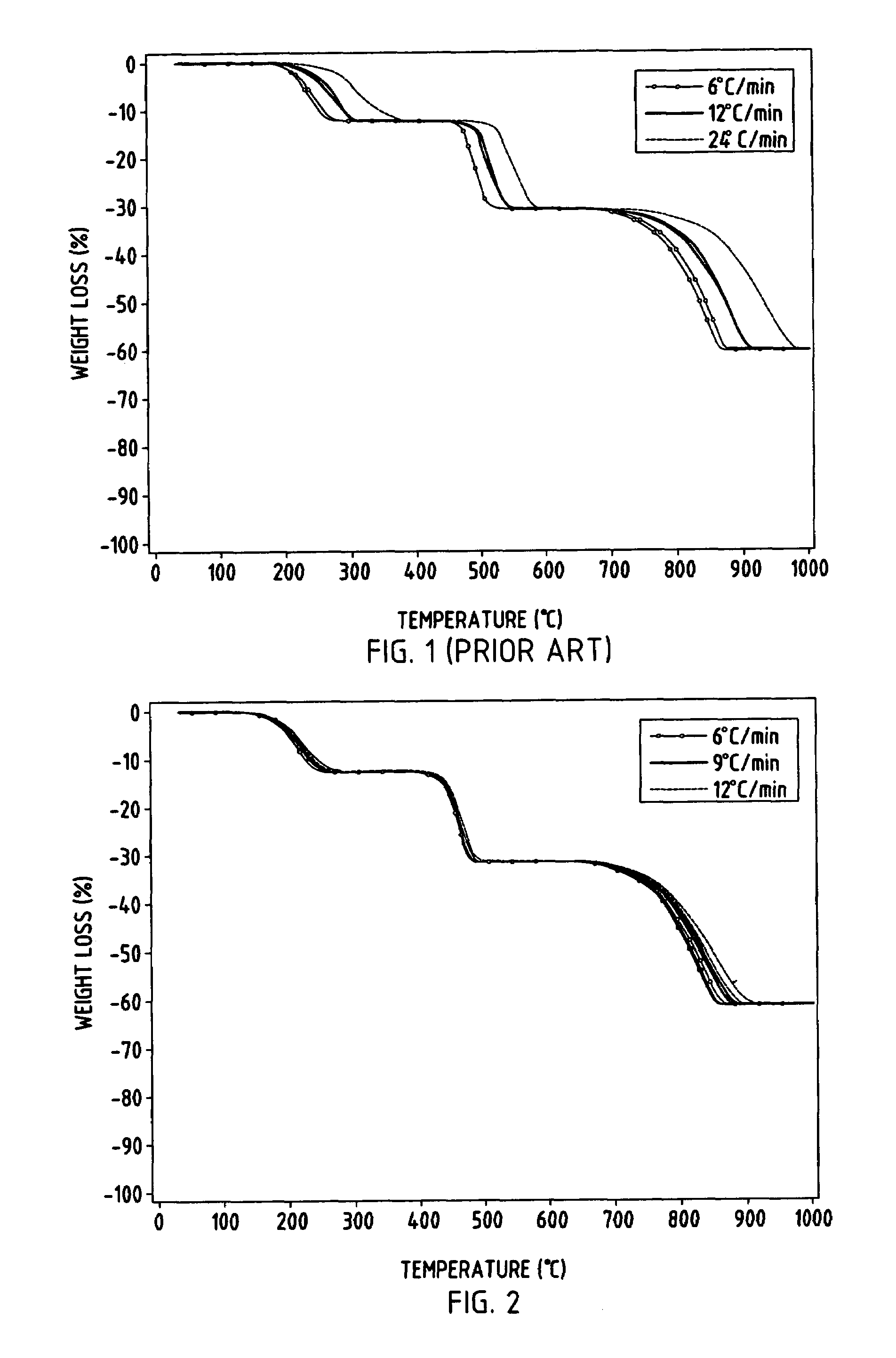
[0019]Referring initially to FIG. 1, there is shown a typical analysis cycle for samples, such as 10 gram samples, in a macro batch thermogravametric analyzer of the prior art, such as disclosed in U.S. Pat. No. 4,522,788. The graph illustrates the percent of weight loss at different temperature levels as the furnace temperature is increased from ambient to a maximum of approximately 1000° C. during an analysis of a sample. As can be seen with the different temperature ramp rates (i.e., 6° C. per minute verses 24° C. per minute), the reported weight loss verses temperature profile of a sample within a crucible varies significantly.

[0020]The graph of FIG. 2 illustrates the improved performance achieved by the thermogravametric analyzer of the present invention using a predictive temperature control employing two sensors, one fixedly located within the furnace and one located within a crucible during a crucible modeling mode. As seen in FIG. 2, the percent weight loss verses temperatu...


PUM

PropertyMeasurementUnit
temperatureaaaaaaaaaa
volumeaaaaaaaaaa

Abstract

An analytical furnace includes a predictive temperature control which is trained to model crucible temperature during analysis by employing a pair of temperature sensors, with one sensor being mounted in the furnace in fixed relationship and a second sensor which can be positioned within a crucible for training and tuning a crucible temperature profile, such that the crucible temperature in which a sample is placed is modeled and its response to the application of energy to the furnace in accordance with the furnace's dynamic thermal characteristics is known. By modeling the temperature profile within a crucible, the furnace can be controlled to provide a faster, more accurate analysis and prevent excessive overshooting of temperature as desired temperature plateaus are approached.

Description

CROSS-REFERENCE TO RELATED APPLICATIONS[0001]This application claims priority under 35 U.S.C. § 119(e) on U.S. Provisional Application No. 60 / 452,594 entitled ANALYTICAL FURNACE WITH PREDICTIVE TEMPERATURE CONTROL, filed on Mar. 6, 2003, by Peter M. Willis, the entire disclosure of which is incorporated herein by reference.BACKGROUND OF THE INVENTION[0002]The present invention relates to an analytical furnace and particularly to an analytical furnace having a predictive temperature control.[0003]Many laboratory analyzers employ combustion or other types of furnaces which heat and / or combust a sample for the determination of chemical elements in the sample. One type of analyzer is a thermogravametric analyzer which employs a furnace, the temperature of which must be carefully controlled. The thermogravametric analyses of materials provide important information as to moisture content, volatiles, ash, or fixed carbon, as well as weight loss or gain on ignition. Materials, such as coal,...

Claims


Application Information

Patent Timeline
Patent Type & Authority Patents(United States)
IPC IPC(8): H05B1/02C30B1/00C30B13/00C30B21/04C30B28/08F27BF27B14/00F27B14/20F27B17/02F27D19/00F27D21/00G01G19/00G01N5/04G01N33/22H05B6/28
CPCF27B14/00F27B14/20F27B17/02F27D19/00G01G19/00G01N5/04H05B6/28F27D21/0014Y10T117/10
Inventor WILLIS, PETER M.
Owner LECO CORPORATION
Why Eureka
Try Eureka