
Method for producing a vertical field effect transistor

a technology of vertical field effect transistor and transistor, which is applied in the direction of transistors, semiconductor devices, electrical equipment, etc., can solve the problems of difficult production, difficult production, and difficulty in optimizing the gate structure, so as to achieve good electrical properties, simple production, and good electrical properties

Inactive Publication Date: 2008-07-29
INFINEON TECH AG
View PDF12 Cites 7 Cited by
  • Summary
  • Abstract
  • Description
  • Claims
  • Application Information

AI Technical Summary

Benefits of technology

[0009]The invention provides a simple method for producing a field effect transistor having very good electrical properties. Moreover, the intention is to specify a field effect transistor having very good electrical properties that is simple to produce, in particular a FLASH memory transistor.
[0011]The above steps are simple to perform and have the consequence that the control electrode can be produced in particular with a rectangular or square cross section. In particular, the width of the control electrode remains the same with increasing distance from the substrate. Tapering sections can be avoided at the control electrode. The control electrode can therefore be produced in a very dimensionally accurate manner and with high positioning accuracy with regard to the projection. Therefore, field effect transistors are produced with mutually identical and particularly good electrical properties.
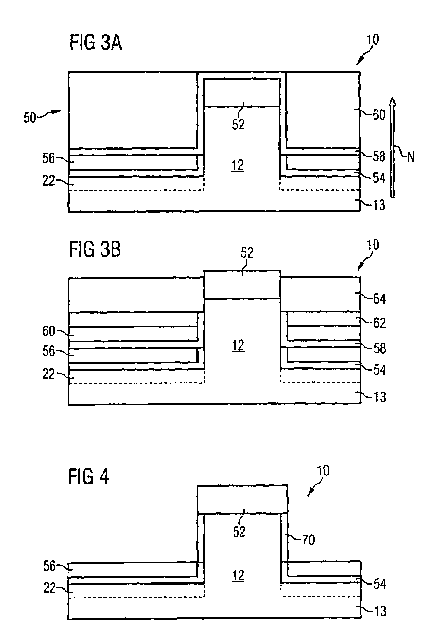
[0017]In another development, prior to the application of the control electrode layer, the spacer layer near to the substrate is planarized and etched back over the whole area, preferably a part of the structure being uncovered. As an alternative the spacer layer near to the substrate can also be applied such that it is only very thin, with the result that etching-back is not necessary. However, etching-back leads to a very dimensionally accurate spacer layer.
[0018]In a another embodiment, after the etching-back of the control electrode layer, an electrically insulating spacer layer remote from the substrate is applied, planarized and etched back over the whole area. In particular the repeated planarization and etching-back in the case of successively applied layers make it possible to achieve a dimensionally accurate three-dimensional integration.
[0023]In yet another embodiment, the structure is formed with the aid of a hard mask, the hard mask being used as a stop layer during all the planarization steps mentioned. It is thus possible to stop very accurately at a predetermined level. Proceeding from this level, it is then possible to perform a time-controlled etching-back process during which it is possible to produce an etched-back layer having a layer thickness in a small tolerance range.
[0026]In another embodiment, the charge storage layer is planarized and subsequently etched back over the whole area, preferably a part of the structure or a part of the insulating layer being uncovered. By means of these steps, it is possible to produce a charge storage layer with a top area that lies parallel to a substrate layer or to the base area. Such a charge storage layer leads to defined programming and erasure operations. In one development, at least one spacer element is formed on the structure and on the charge storage layer. The spacer element then serves for the patterning of the charge storage layer, so that a simple self-aligning spacer technique is used for patterning.

Problems solved by technology

Conventional planar field effect transistors cannot meet these requirements.
However, multiple gate structures have drawbacks.
For example multiple gate structures are three-dimensional structures, so that their production is difficult and must be carefully optimized.
Different thicknesses are not simple to realize in a normal CMOS flow.

Method used


Image

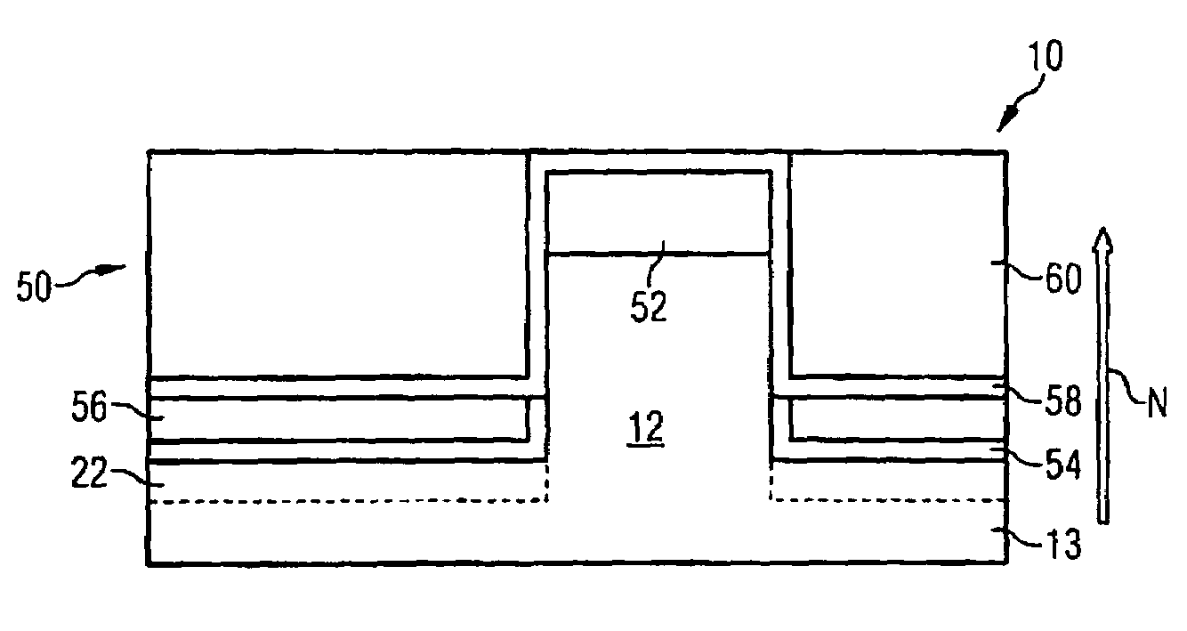
  • Method for producing a vertical field effect transistor
  • Method for producing a vertical field effect transistor
  • Method for producing a vertical field effect transistor

Examples


Embodiment Construction

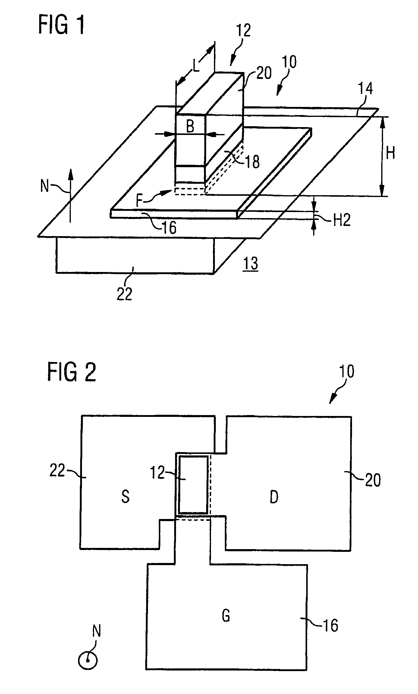
[0036]FIG. 1 shows a vertical fin field effect transistor 10 formed on a fin 12. The fin 12 has been etched from a semiconductor substrate 13, which has a planar substrate surface 14 after etching. By way of example, a silicon substrate which is initially predoped or undoped is used. The fin 12 may have a height H of 100 nanometers in the direction of the normal N to the substrate surface 14. The width B of the fin 12 is e.g. 20 nanometers. The length L of the fin 12 is e.g. 60 nanometers.

[0037]At the foot F of the fin 12 or at the base of the fin 12, a base area of the fin 12 is situated in the plane of the substrate surface 14. A gate electrode 16 encloses the fin 12 and lies parallel to and at a distance from the substrate surface 14. The distance may be 30 nanometers. The gate electrode 16 comprises doped polycrystalline silicon.

[0038]A gate dielectric 18 (not illustrated in FIG. 1) is situated between the gate electrode 16 and the fin 12. Suitable gate dielectrics are silicon d...


PUM


Abstract

A method for producing a field effect transistor, in which a plurality of layers are in each case deposited, planarized and etched back, in particular a gate electrode layer, is disclosed. This method allows the manufacturing of transistors having outstanding electrical properties and having outstanding reproducibility.

Description

CROSS REFERENCE TO RELATED APPLICATIONS[0001]This application is a continuation of international application PCT / EP2004 / 052485, filed Oct. 8, 2004, which claims priority to German patent application serial number DE 10350751.5, filed Oct. 30, 2003.BACKGROUND[0002]1. Field of the Invention[0003]The invention relates to a method for producing a vertical field effect transistor.[0004]2. Description of the Related Art[0005]The field effect principle consists in influencing the current flow in a channel by means of the potential at a control electrode. The control electrode is also referred to as the gate. The field effect transistors for logic circuits are intended to have a short gate length, a thin gate dielectric and, at the same time, a large switch-on current. Moreover, the operating voltage is intended to be as small as possible in order to avoid excessively large leakage currents through the thin gate dielectric. Conventional planar field effect transistors cannot meet these requ...

Claims


Application Information

Patent Timeline
Patent Type & Authority Patents(United States)
IPC IPC(8): H01L21/336H01L21/28H01L29/78H01L29/786H01L29/788H01L29/792
CPCH01L21/28273H01L21/28282H01L29/66666H01L29/66742H01L29/66825H01L29/7828H01L29/78642H01L29/7883H01L29/7885H01L29/66833H01L29/792H01L29/40114H01L29/40117
Inventor TEWS, HELMUT
Owner INFINEON TECH AG
Learn More