
Underwater acoustic beacon and method of operating same for navigation

a technology of underwater acoustic beacons and beacons, which is applied in the field of underwater acoustic beacons and the method of operating beacons for underwater navigation, can solve the problems of adding to the cost and complexity of underwater vehicles

Inactive Publication Date: 2008-07-29
USA REPRESENTED BY THE SEC OF THE NAVY
View PDF2 Cites 18 Cited by
  • Summary
  • Abstract
  • Description
  • Claims
  • Application Information

AI Technical Summary

Benefits of technology

[0004]Accordingly, it is an object of the present invention to provide an underwater acoustic beacon useful in underwater vehicle formation swimming, tracking or docking.

Problems solved by technology

Time-of-flight systems require the use of arrays of transducers at a reference position along with complicated signal processing computations.
Acoustic interrogation systems require two-way communication between a reference position and an object position, a situation that may cause problems for covert operations.
Furthermore, the object position (e.g., a moving underwater vehicle) must generally be equipped to establish or determine its own position, which adds to the cost and complexity of the underwater vehicle.

Method used


Image

  • Underwater acoustic beacon and method of operating same for navigation
  • Underwater acoustic beacon and method of operating same for navigation
  • Underwater acoustic beacon and method of operating same for navigation

Examples


Embodiment Construction

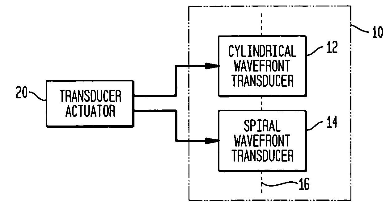
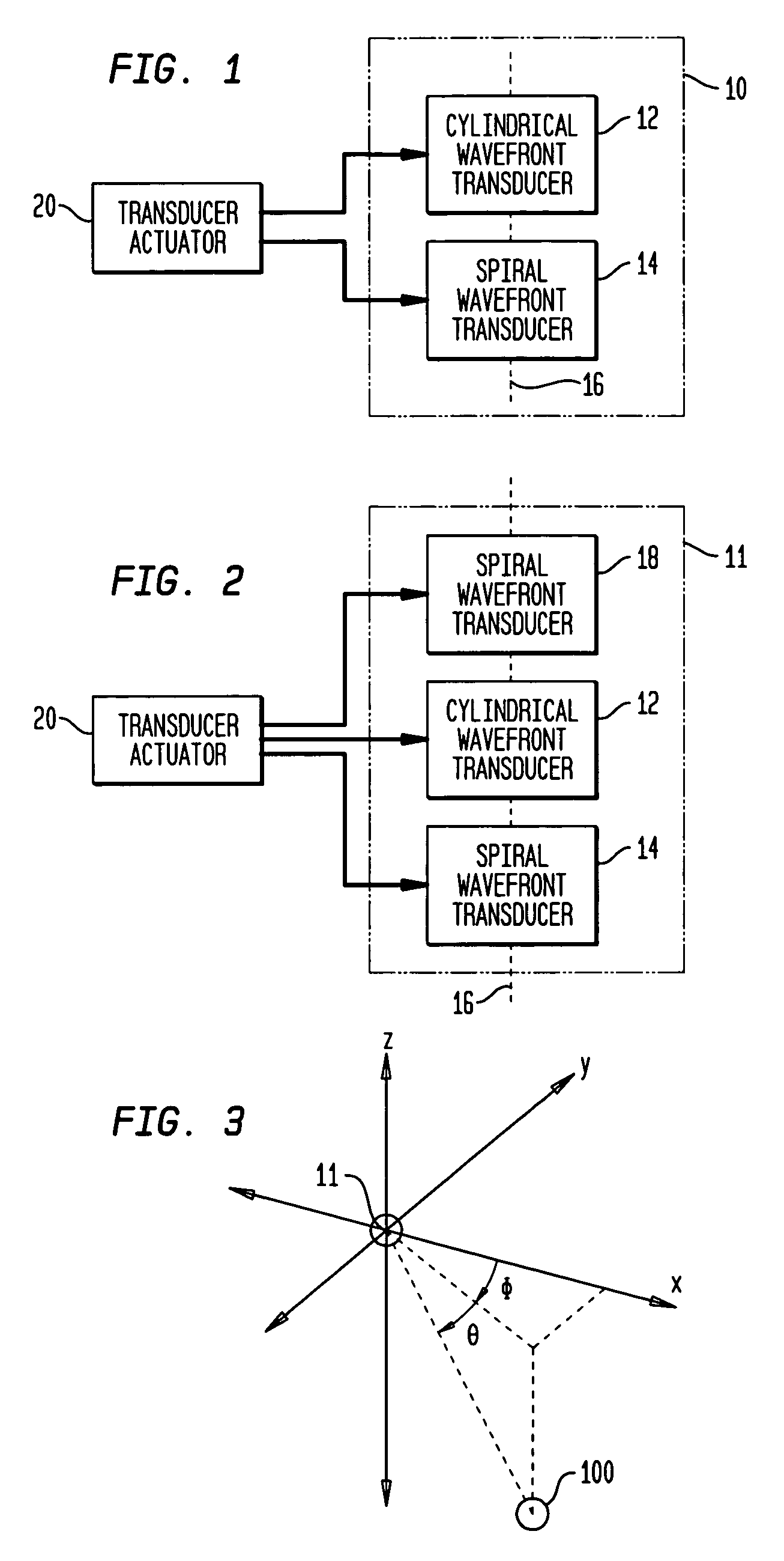
[0021]Referring now to the drawings, and more particularly to FIGS. 1 and 2, two embodiments of an underwater acoustic beacon in accordance with the present invention are shown and are referenced generally by numeral 10 (FIG. 1) and numeral 11 (FIG. 2). Each acoustic beacon can be used in a variety of situations where an underwater vehicle is either being tracked or must home in on a position. Regardless of the application, the output of the acoustic beacon is used passively as will be explained further below.

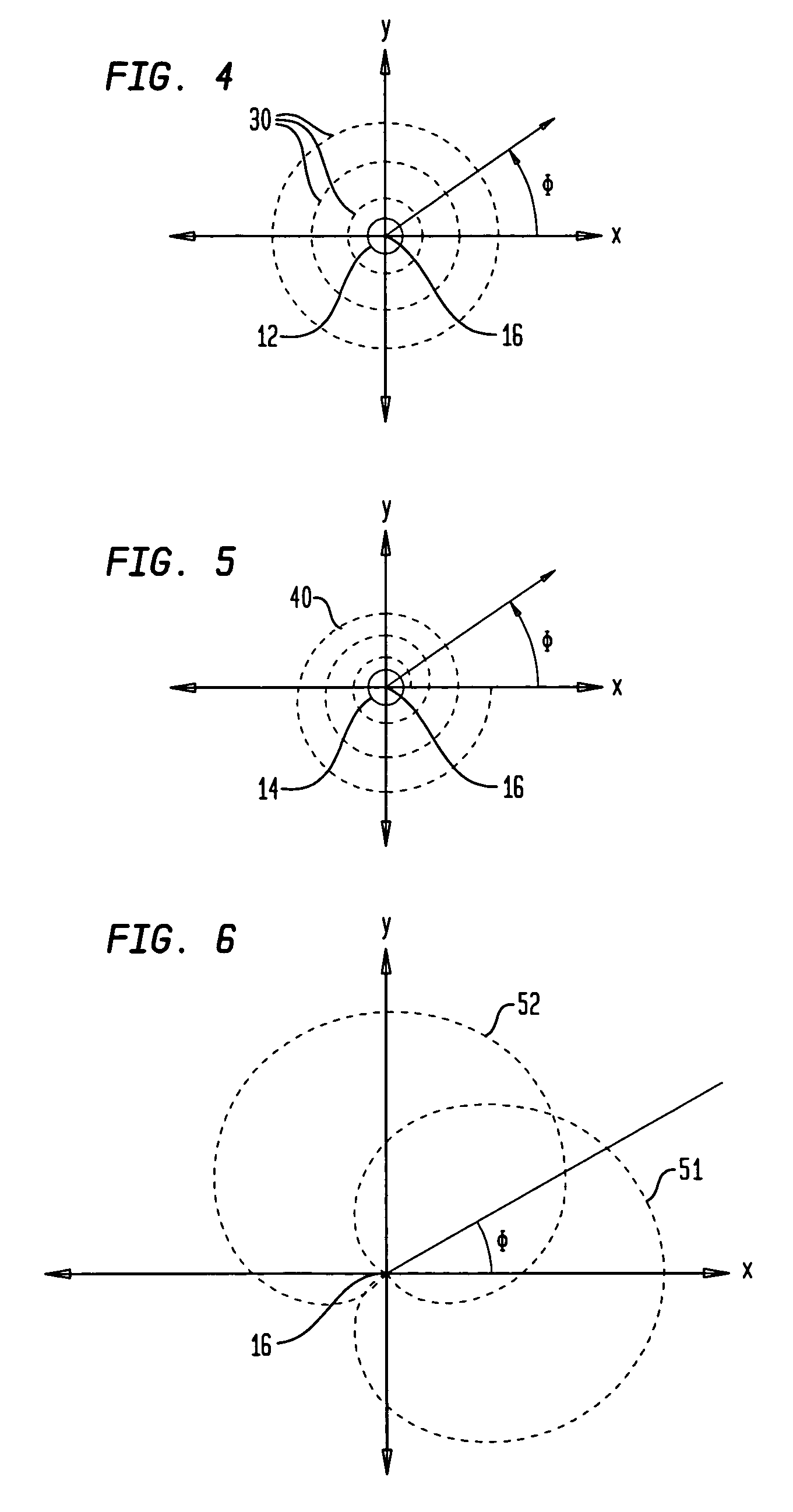
[0022]In general, acoustic beacons 10 and 11 utilize two different types of acoustic transducers to generate distinct acoustic signals. Comparison of the amplitudes of the signals at a detection location provide a heading between the beacon and the detection location. The reference frame is illustrated graphically in FIG. 3 where, for example, acoustic beacon 11 is designated as the origin of an (x,y,z) coordinate system and a detection location is indicated by reference numera...


PUM


Abstract

An underwater acoustic beacon comprises a cylindrical transducer and at least one spiral wavefront transducer aligned along a common central axis. For use in underwater navigation, the cylindrical and spiral wavefront transducers are activated singly and in combination in accordance with a prescribed sequence.

Description

ORIGIN OF THE INVENTION[0001]The invention described herein was made in the performance of official duties by an employee of the Department of the Navy and may be manufactured, used, licensed by or for the Government for any governmental purpose without payment of any royalties thereon.FIELD OF THE INVENTION[0002]The invention relates generally to acoustic signal sources and navigation, and more particularly to an underwater acoustic beacon and method of operating the beacon for underwater navigation.BACKGROUND OF THE INVENTION[0003]Current underwater acoustic systems use time-of-flight or interrogation to control underwater vehicle formation “swimming”, tracking and / or docking. Time-of-flight systems require the use of arrays of transducers at a reference position along with complicated signal processing computations. Acoustic interrogation systems require two-way communication between a reference position and an object position, a situation that may cause problems for covert opera...

Claims


Application Information

Patent Timeline
Patent Type & Authority Patents(United States)
IPC IPC(8): H04B1/02
CPCG01S1/82
Inventor DZIKOWICZ, BENJAMIN
Owner USA REPRESENTED BY THE SEC OF THE NAVY
Learn More