
Underwater navigation system

a communication system and navigation system technology, applied in the field of underwater communications system, can solve the problems of virtually unusable, limited functionality, subject to multi-path effects,

Inactive Publication Date: 2010-04-08
WIRELESS FIBER SYST
View PDF12 Cites 19 Cited by
  • Summary
  • Abstract
  • Description
  • Claims
  • Application Information

AI Technical Summary

Benefits of technology

This approach significantly improves the distance and data rate of underwater communication systems by minimizing signal attenuation and bandwidth restrictions, enabling effective communication over longer ranges with reduced bit rates and lower signal frequencies.

Problems solved by technology

A problem with such systems is that they are degraded by noise and interference from a number of sources.
They are also subject to multi-path effects and in some environments are virtually unusable.
Whilst the communications systems of WO01 / 95529 and GB2163029 have some technical advantages over more conventional acoustic or radio link systems, the functionality described is limited, and for many practical applications the available bandwidth is highly restrictive, as is distance over which data can be transmitted.
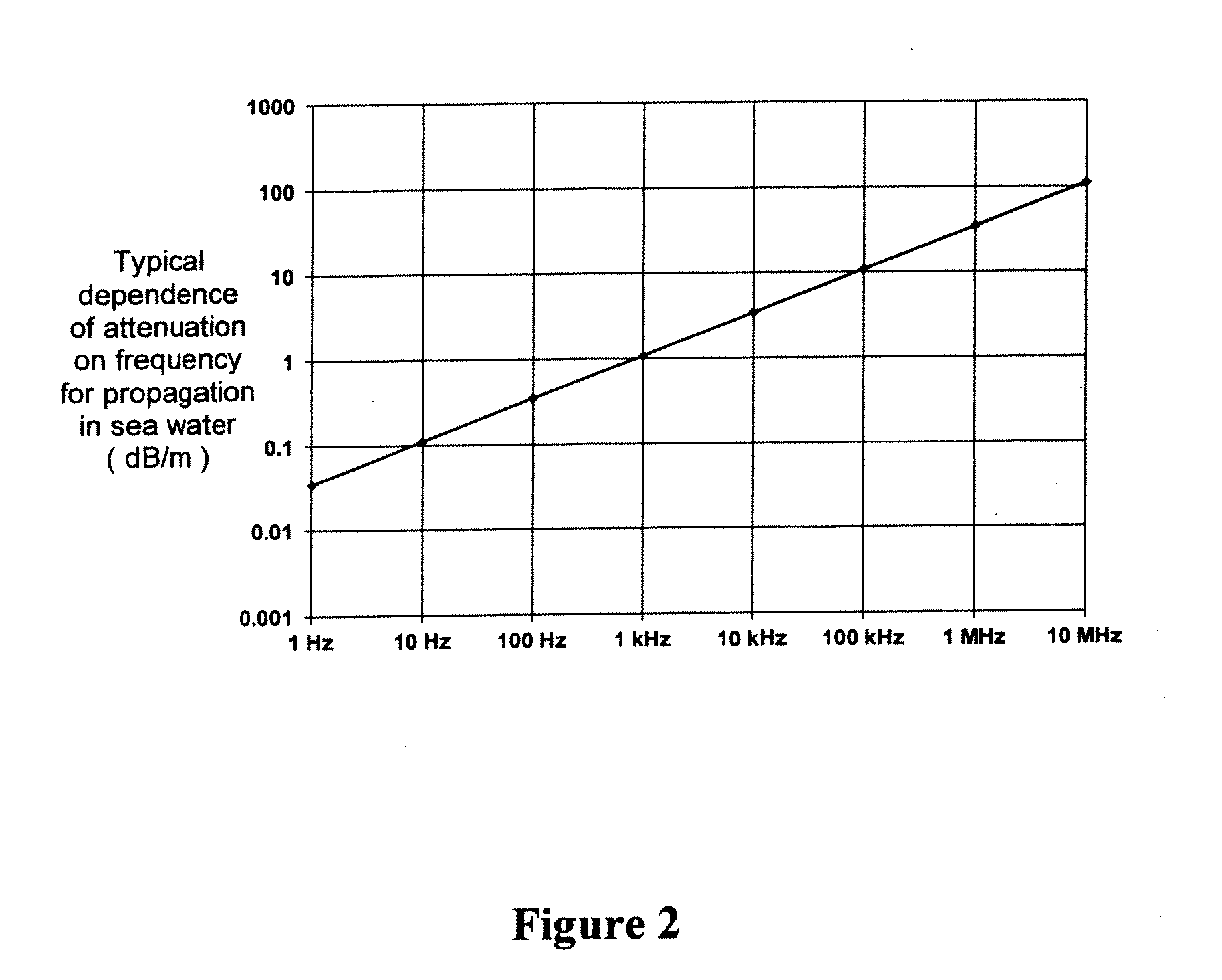
However, for propagating electromagnetic waves the energy is continually cycling between magnetic and electric field and this results in attenuation of propagating waves due to conduction losses.
The attenuation losses, the bandwidth restrictions and the limited distances over which data can be transmitted all pose significant practical problems for underwater communications.
Existing methods of acoustic communication are inherently restricted in the distance they can achieve at effective data rates.
The existing art of electromagnetic communication under water fails to recognize measures that can be taken to maximize the distance and / or useful information rate which can be achieved by adapting the devices sourcing and using the information so that more effective signal frequencies can be adopted.

Method used


Image

  • Underwater navigation system
  • Underwater navigation system
  • Underwater navigation system

Examples


Embodiment Construction

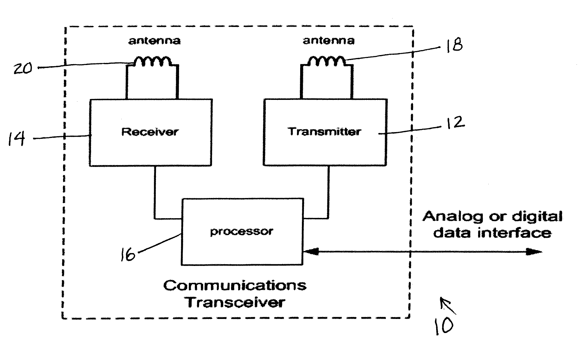
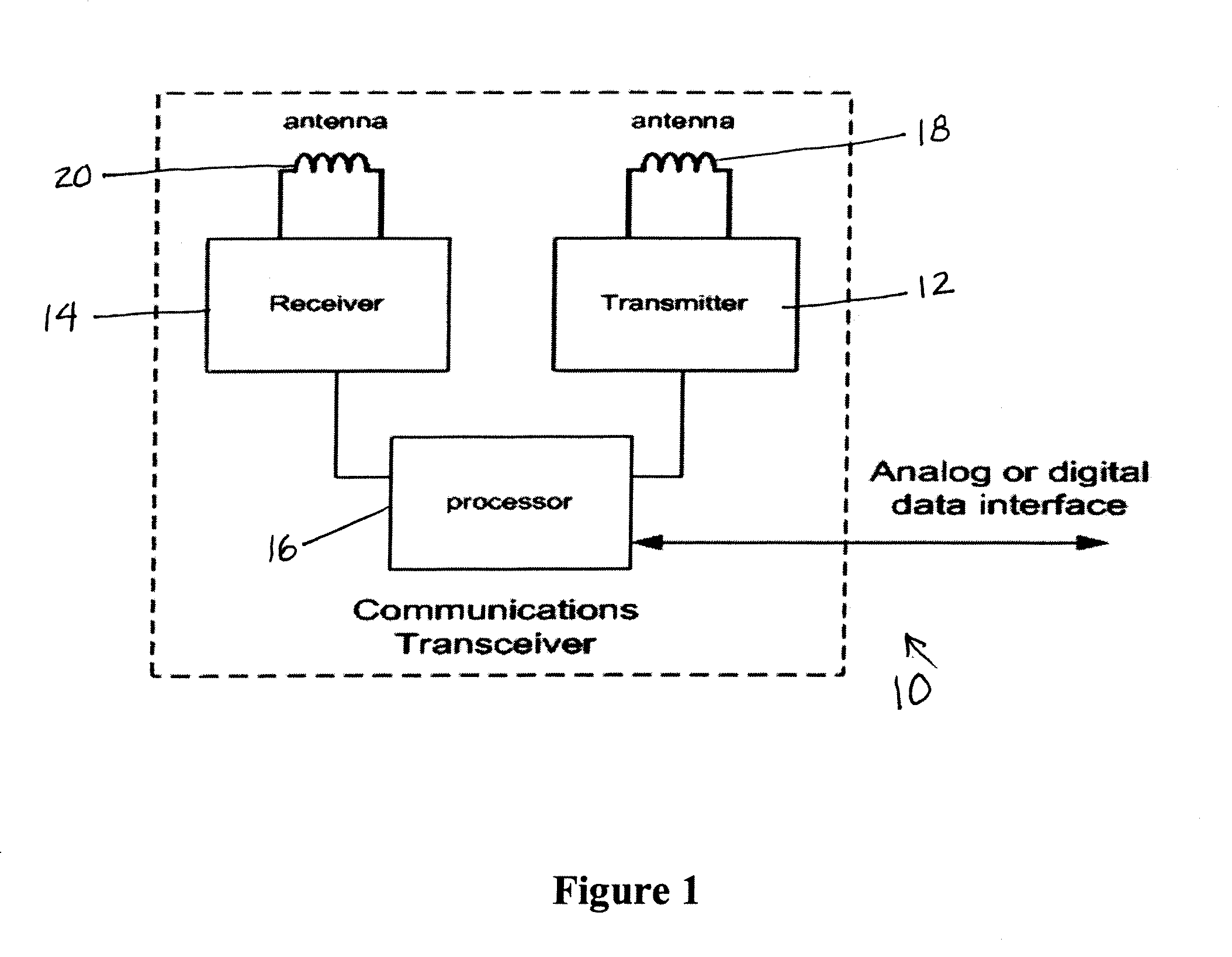
[0034]In various embodiments, the present invention relates to underwater communication systems, and their methods of use, that use electromagnetic signals as the communicating means. Each of these uses a communications transceiver 10 that has a transmitter 12, a receiver 14 and a processor 16 which can be connected to an analogue or digital data interface (not shown), as illustrated in FIG. 1. Both the transmitter and receiver 12 and 14 respectively have a waterproof, electrically insulated magnetic coupled antenna 18 and 20. Alternatively a single antenna can be shared between transmitter and receiver. A magnetic coupled antenna is used because water is an electrically conducting medium, and so has a significant impact on the propagation of electromagnetic signals. Ideally, each insulated antenna assembly is surrounded by a low conductivity medium that is impedance matched to the propagation medium, for example distilled water.

[0035]Electrically insulated magnetic coupled antennas...


PUM


Abstract

An underwater communications system is provided that transmits electromagnetic and / or magnetic signals to a remote receiver. The transmitter includes a data input. A digital data compressor compresses data to be transmitted. A modulator modulates compressed data onto a carrier signal. An electrically insulated, magnetic coupled antenna transmits the compressed, modulated signals. The receiver has an electrically insulated, magnetic coupled antenna for receiving a compressed, modulated signal. A demodulator is provided for demodulating the signal to reveal compressed data. A de-compressor de-compresses the data. An appropriate human interface is provided to present transmitted data into text / audio / visible form. Similarly, the transmit system comprises appropriate audio / visual / text entry mechanisms.

Description

CROSS-REFERENCE TO RELATED APPLICATION[0001]This application claims the benefit of Ser. No. 60 / 690,964, 60 / 690,966, and 60 / 690,959, all filed Jun. 15, 2005, and is a continuation in part of GB0602398.0, filed Feb. 7, 2006, which applications are fully incorporated herein by reference.FIELD OF USE[0002]The present invention relates generally to an underwater communications system, and its methods of use, and more particularly to an underwater communications system that uses electromagnetic propagation and magnetic induction transmission, and optimizes the distance which can be achieved by digital transmission of information.DESCRIPTION OF THE RELATED ART[0003]Various underwater communication systems are known. One of the most common is based on acoustic techniques. A problem with such systems is that they are degraded by noise and interference from a number of sources. They are also subject to multi-path effects and in some environments are virtually unusable. Other underwater commun...

Claims


Application Information

Patent Timeline
Patent Type & Authority Applications(United States)
IPC IPC(8): H04B11/00
CPCH04B13/02Y10S367/904Y10S367/91Y10S367/901
Inventor RHODES, MARKWOLFE, DEREKHYLAND, BRENDAN
Owner WIRELESS FIBER SYST
Learn More