Central vacuum system with secondary airflow path

a vacuum system and secondary airflow technology, applied in the direction of vehicle maintenance, sport apparatus, application, etc., to achieve the effect of convenient assembly, repair and operation

Active Publication Date: 2008-08-05
BRUNEAU MARC
View PDF21 Cites 22 Cited by
  • Summary
  • Abstract
  • Description
  • Claims
  • Application Information

AI Technical Summary

Benefits of technology

[0011]Another object of some embodiments is to help prevent carbon dust from a motor's commutator brushes from contaminating a motor drive component or its associated circuit board.
[0014]Another object of some embodiments is to provide a central vacuum system with a filter for carbon dust without having to install the motor's drive components on the exterior of the vacuum canister.
[0016]Another object of some embodiments is to cool a vacuum motor's drive components with a relatively cool, low volume of air, and to cool the motor itself with warmer air but at a higher volume.
[0019]Another object of some embodiments is to position a motor chamber and an electrical chamber between an upper plenum and a lower suction chamber to facilitate the assembly, repair and operation of a central vacuum system.
[0020]Another object of some embodiments is to install a motor's electrical components inside a central vacuum canister with the cylindrical sidewall of the canister supporting the weight of the components, thereby eliminating the need for an exterior mounted electrical box.

Problems solved by technology

The cooling air, unfortunately, may entrain carbon dust from the motor's commutator brushes and deposit a carbon residue on the exterior of the machine.
Although such filters help keep the machine clean, they also create an airflow restriction that may lead to overheating.

Method used


Image

  • Central vacuum system with secondary airflow path
  • Central vacuum system with secondary airflow path
  • Central vacuum system with secondary airflow path

Examples


Embodiment Construction

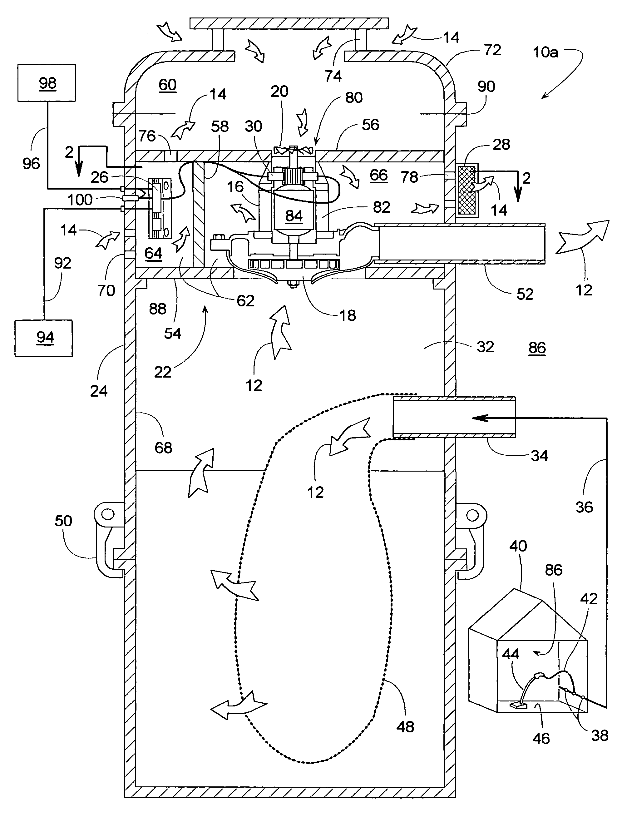
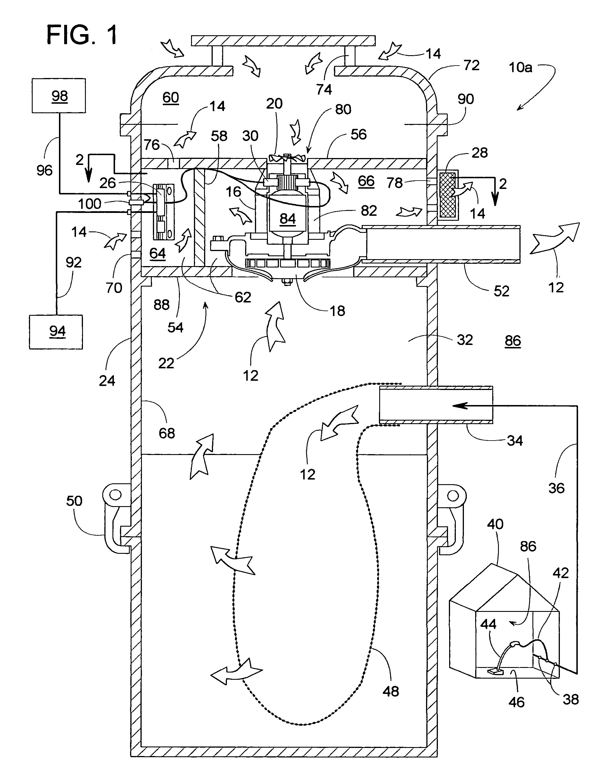
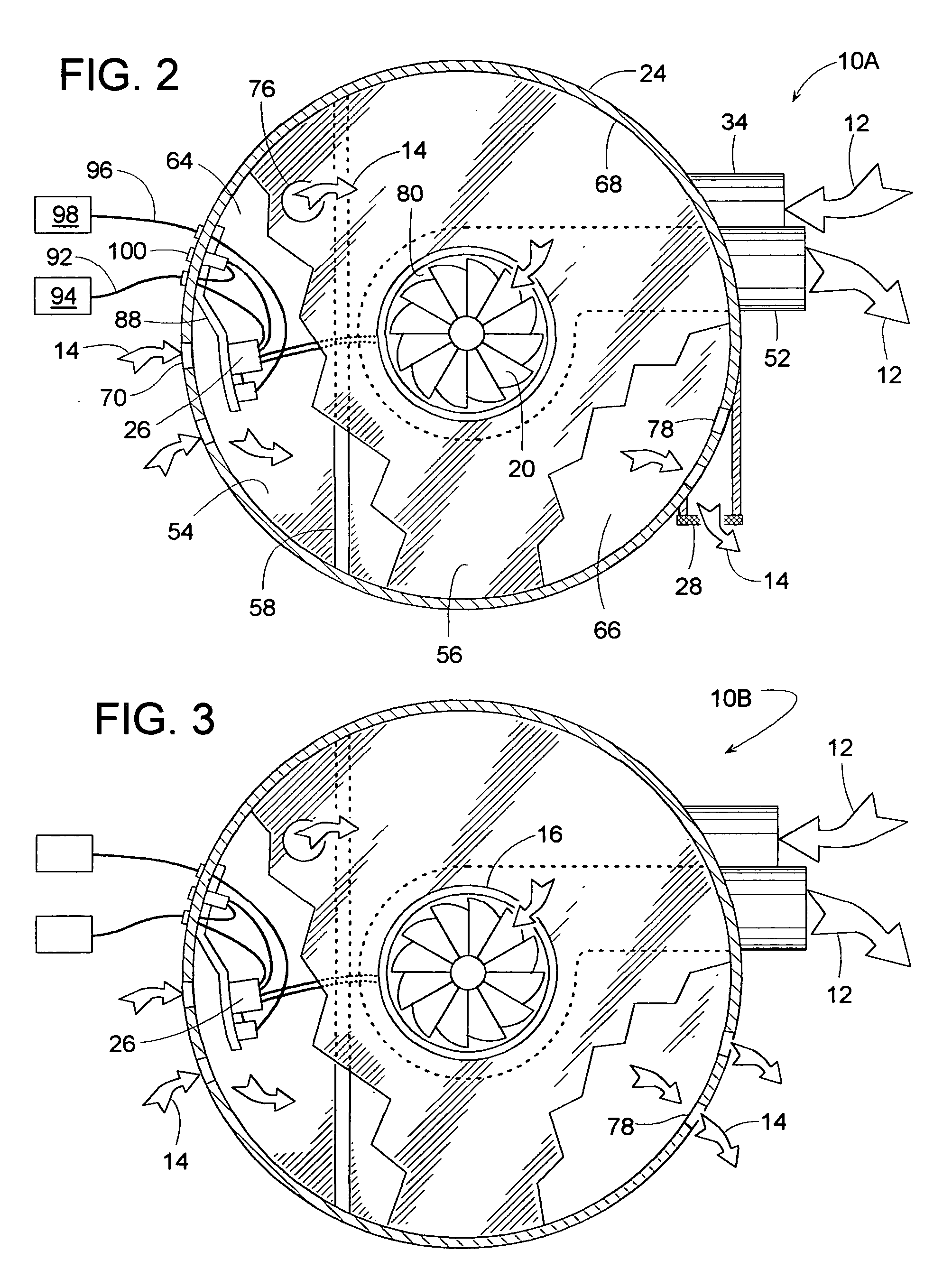
[0028]FIGS. 1 and 2 show a vacuum system 10 that conveys primary air 12 for cleaning (larger arrows) and conveys secondary air 14 for cooling (smaller arrows). A motor 16 drives both a main impeller 18 for moving primary air 12 and a fan or secondary impeller 20 for moving cooling air 14. A divider system 22 installed within a cylindrical or otherwise tubular canister 24 divides the canister into various chambers and directs secondary air 14 in a flow pattern suitable for cooling motor 16 and for cooling at least one motor drive component 26 (e.g., triac). The flow pattern is such that air 14 provides ample cooling even though the airflow is partially restricted by a secondary filter 28 that captures carbon dust emitted from the motor's commutator brushes 30.

[0029]In operation, main impeller 18 draws air 12 from within a suction chamber 32 of canister 24, which is installed at a generally fixed location. A suction inlet 34 connects suction chamber 32 to a network of tubing 36 that l...


PUM


Abstract

A central vacuum system includes a motor-cooling airflow path that provides sufficient cooling for the motor and its drive components even though the cooling air is partially restricted by a downstream filter that captures airborne carbon dust emitted from the motor's commutator brushes. A divider system creates multiple chambers within the vacuum system's canister, and in some embodiments, air passageways in the canister and in the divider system direct the cooling air through the chambers in a flow pattern that avoids contaminating the drive components with carbon dust.

Description

BACKGROUND OF THE INVENTION[0001]1. Field of the Invention[0002]The subject invention generally pertains to central vacuum systems and more particularly to a motor-cooling airflow path for such a system.[0003]2. Description of Related Art[0004]Typical central vacuum systems comprise a blower or vacuum motor that creates a vacuum within a stationary canister. A network of tubing usually connects the canister to several wall-mounted inlet ports that are installed at various locations throughout a house or building. A flexible hose can connect a portable vacuum tool to any of the inlet ports, so the tool can be used for vacuuming a floor or other surface. The vacuum motor draws dust-laden air in series through the tool, through the hose, through the tubing network and into the canister where the dust collects. The canister can be manually opened to empty it periodically.[0005]There are two main types of central vacuum system: cyclonic and filtered. With a cyclonic system, structure wit...

Claims


Application Information

Patent Timeline
Patent Type & Authority Patents(United States)
IPC IPC(8): A47L5/38A47L9/22
CPCA47L5/22A47L9/2889A47L9/22A47L5/38
Inventor BRUNEAU, MARC
Owner BRUNEAU MARC
Why Eureka
Try Eureka