Pump system and axle-driving system

a technology of axle drive and pump system, which is applied in the direction of mechanical equipment, transportation and packaging, electric propulsion mounting, etc., can solve the problems of insufficient cooling efficiency of conventional pump system, inability to expect a sufficient cooling effect, and inability to describe how the capacity and size of the brake unit could be reduced, so as to achieve enhanced piping workability

Active Publication Date: 2008-08-05
KANZAKI KOKYUKOKI MFG
View PDF18 Cites 18 Cited by
  • Summary
  • Abstract
  • Description
  • Claims
  • Application Information

AI Technical Summary

Benefits of technology

[0018]With the pump system according to the present invention, it is possible to effectively prevent the oil from being retained within the PTO clutch accommodating space by means of a pump action accompanied with rotating motions of the first and second transmission gears, so that it is possible to improve a cooling efficiency for the PTO clutch mechanism.
[0024]Preferably, the first and second suction / discharge ports are provided in the vicinity of an outer peripheral edge of the first or second transmission gear, and the housing has a partition portion for preventing a direct oil flow between the first and second suction / discharge ports.
[0049]An axle-driving system according to the present invention is so constructed that the output of the motor unit is transmitted to the drive axle via the reduction transmission unit. Therefore, a motor unit of low-torque and high-speed type, which is highly reliable and compact, can be used as the motor unit.
[0050]In addition, the system is so constructed that a brake force is applied to the motor shaft prior to deceleration by the reduction transmission unit, and thus the capacity reduction and miniaturization of the brake unit can be achieved.
[0051]Furthermore, since the brake unit is not inserted into the reduction transmission unit, distances between the motor shaft, the intermediate shaft in the reduction transmission unit and the drive axle can be shortened. This effectively enables the miniaturization of the entire apparatus in the radial direction with respect to the drive axle.
[0058]Such a construction allows the conduit arrangements of the pair of right and left axle-driving systems to be the same, thereby piping workability could be enhanced.

Problems solved by technology

However, the conventional pump system does not sufficiently take cooling efficiency for a PTO clutch mechanism in the PTO unit into consideration.
However, in the case that the reserved oil is retained, it is impossible to expect a sufficient cooling effect.
Neither of the prior art documents, however, mentions such a brake unit, and, of course, there is no description as to how the brake unit could be reduced in its capacity and size.

Method used


Image

  • Pump system and axle-driving system
  • Pump system and axle-driving system
  • Pump system and axle-driving system

Examples


embodiment 1

[0081]Hereinafter, a preferable embodiment of a pump system according to the present invention will be described with reference to the accompanying drawings.

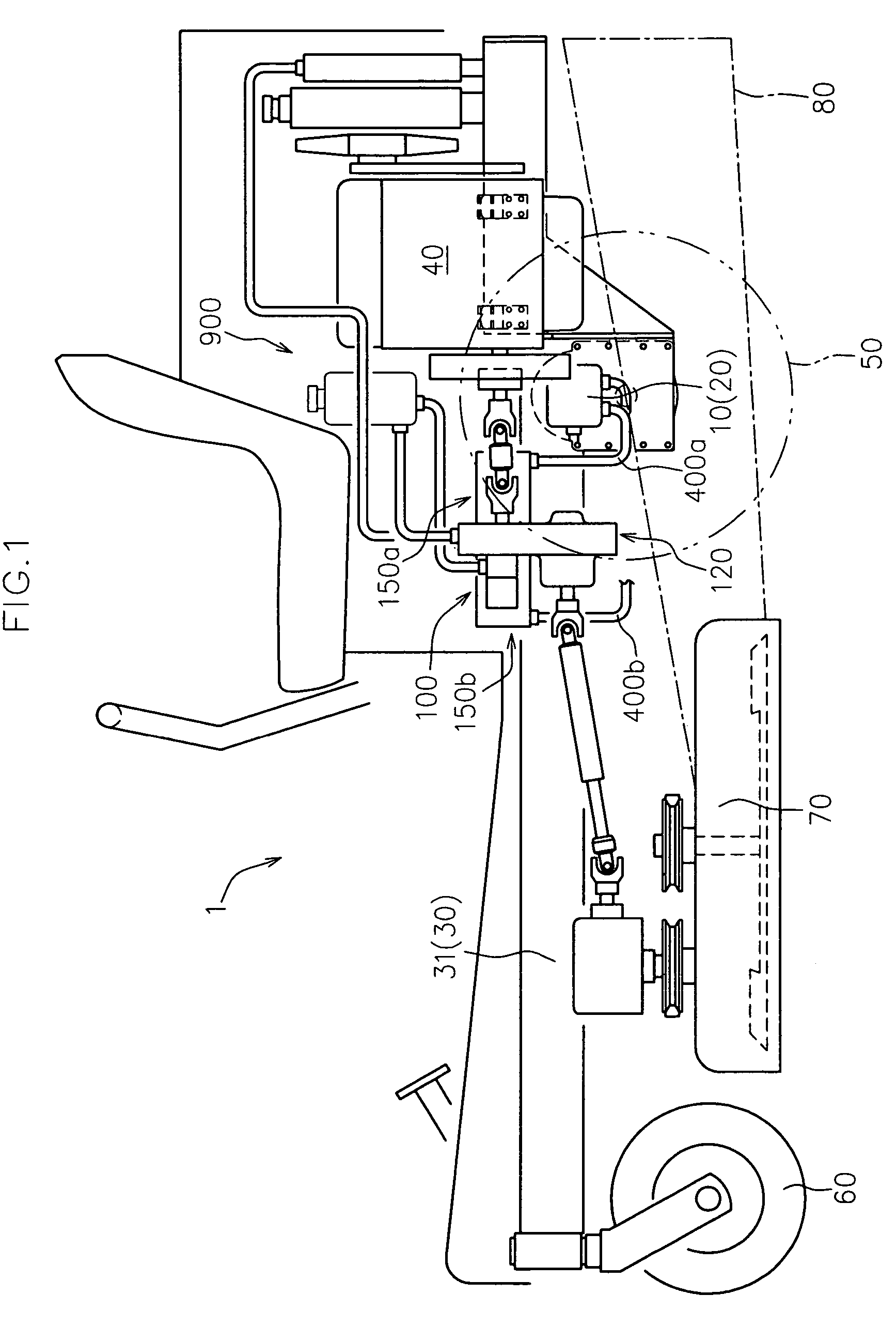
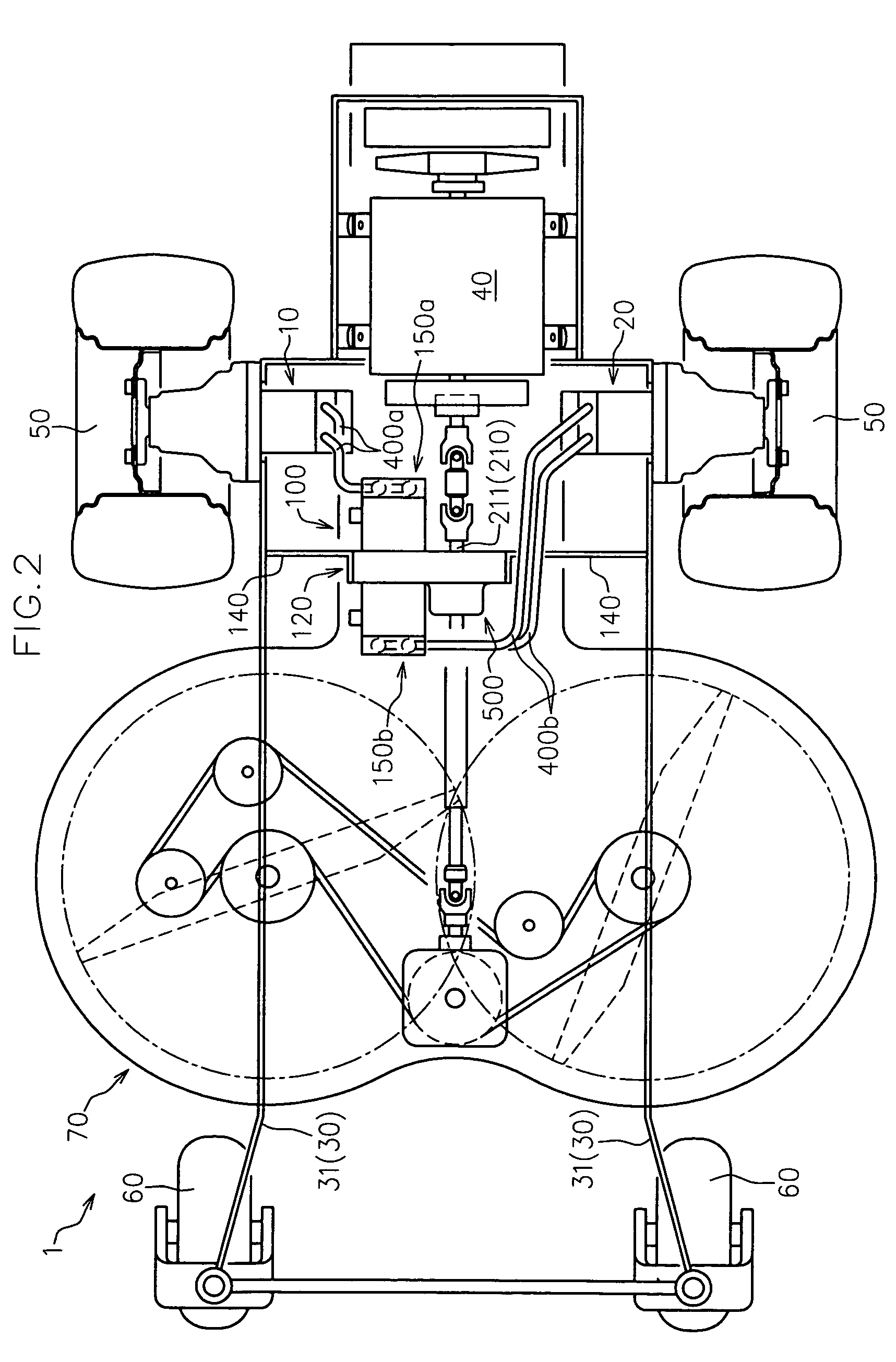
[0082]FIGS. 1 and 2 are respectively a side view and a plan view of a working vehicle 1 to which a pump system 100 in accordance with this embodiment is applied. FIG. 3 is a hydraulic circuit diagram of the working vehicle 1.

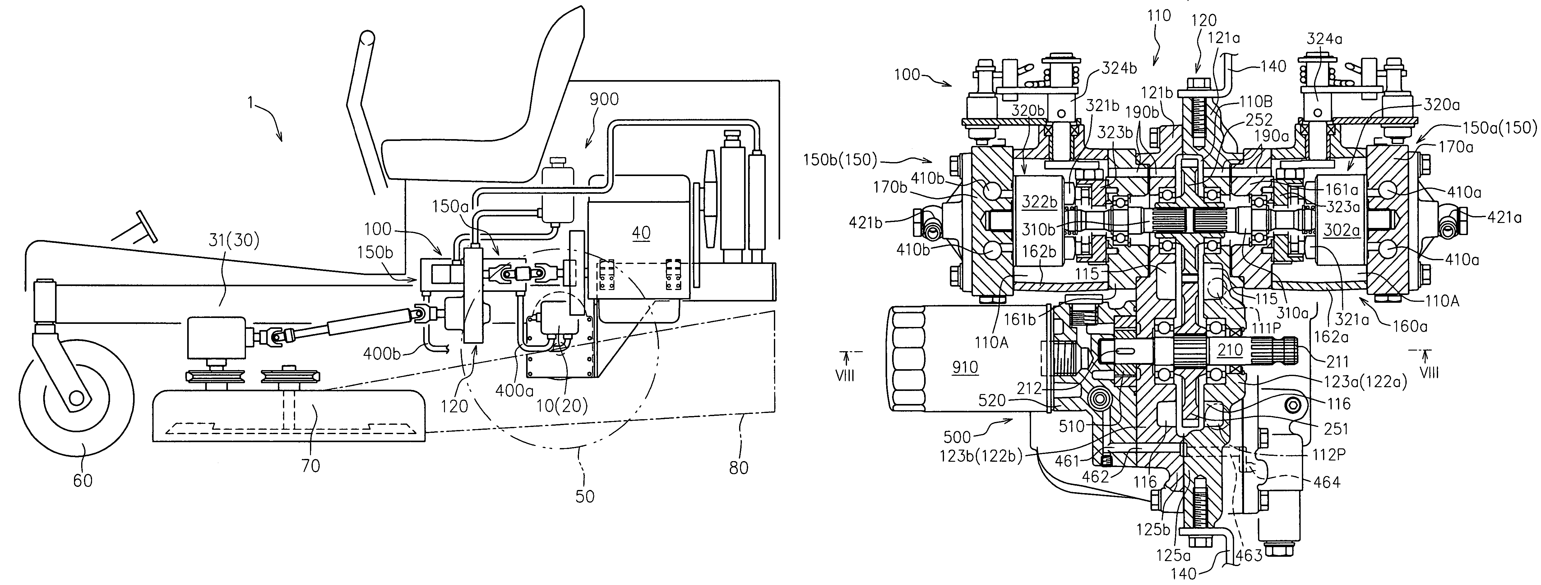
[0083]As shown in FIGS. 1 and 2, the working vehicle 1 includes a vehicle frame 30, a driving source 40 mounted to the vehicle frame 30, the pump system 100 operatively connected to the driving source 40, a pair of first and second hydraulic motor units 10 and 20 hydraulically connected to the pump system 100, and a pair of right and left driving wheels 50 respectively driven by the pair of first and second hydraulic motor units 10 and 20.

[0084]The pump system 100 forms a non-stepwise speed change device for traveling in cooperation with the pair of first and second hydraulic motor units 10 and 20 of the wor...

embodiment 2

[0212]A preferred embodiment of an axle-driving system according to another aspect of the present invention will be described below with reference to the accompanying drawings.

[0213]An axle-driving system according to the present invention includes a motor unit which forms a non-stepwise speed change in cooperation with an actuator such as a hydraulic pump unit and drives a corresponding drive axle, so that the axle-driving system drives the corresponding drive axle with changing its rotational speed in cooperation with the actuator.

[0214]It should be noted that this embodiment is described with an example in which a hydraulic pump unit is used as the actuator and a hydraulic motor unit which constitutes HST in cooperation with the hydraulic pump unit is used as the motor unit. However, an axle-driving system according to the present invention also covers an embodiment in which an electric motor unit is used as the motor unit. When such an electric motor unit is used, an electric ge...

embodiment 3

[0297]An axle-driving system according to another embodiment of the present invention will be described below with reference to the accompanying drawings.

[0298]FIG. 17 is a front sectional view of the axle-driving system 10B according to this embodiment.

[0299]It should be noted that the identical components to those in the embodiment 2 are denoted by the identical numerals in this FIG., and their detailed descriptions are omitted.

[0300]As shown in FIG. 17, the axle-driving system 10B according to this embodiment is identical to the axle-driving system 10A according to the embodiment 2 except that the motor case body 1110 is integrally formed with the inner case member 1020 of the axle case 1000.

[0301]Also in the axle-driving system 10B having such a construction, the capacity reduction and cost reduction of the brake unit 1600 can be achieved and the miniaturization of the entire apparatus with respect to the radial direction of the drive axle 50a can be achieved.


PUM


Abstract

A pump system includes a housing, an input shaft, a pump shaft; a hydraulic pump body, a PTO shaft, a power transmission gear train, and a PTO clutch mechanism. The housing has a narrow gear accommodating space surrounding a region including a mesh point between the first and second transmission gears of the power transmission gear train, a PTO clutch accommodating space which surrounds the PTO clutch mechanism and which is fluidly communicated with the gear accommodating space, and a pair of first and second suction / discharge ports which communicate the internal space of the housing with an outside of the housing. The first suction / discharge port is arranged within the gear accommodating space so as to be positioned in an opposite side to the PTO clutch accommodating space with the mesh point between the first and second transmission gears interposed therebetween.

Description

BACKGROUND OF THE INVENTION[0001]1. Field of the Invention[0002]The present invention relates to a pump system provided with a hydraulic pump body and a PTO unit, and an axle-driving system which is provided for each drive axle and independently drives the corresponding drive axle in cooperation with an actuator.[0003]2. Background Art[0004]There has been conventionally used in various fields a pump system which includes a hydraulic pump body and a PTO unit and has a structure that an input from a driving source is input to both of the hydraulic pump body and the PTO unit (see, for example, JP-A 2003-291674).[0005]Such a pump system is particularly useful in a working vehicle or the like, for example, because the hydraulic pump body can form a travel transmission path in cooperation with an actuator such as a hydraulic motor body or the like arranged apart from the pump system, and the PTO unit can form a PTO transmission path for transmitting a power to an external working machine....

Claims


Application Information

Patent Timeline
Patent Type & Authority Patents(United States)
IPC IPC(8): B60K17/10
CPCA01D69/002B60K17/28B60K25/06B60Y2200/223Y10T74/19149
Inventor YASUDA, TOSHIFUMISAKIKAWA, SHIGENORIKITAGAWARA, HIROSHI
Owner KANZAKI KOKYUKOKI MFG
Why Eureka
Try Eureka