Progressing cavity pump or motor

a technology of progressing cavity and pump, which is applied in the direction of positive displacement liquid engine, radial flow pump, rotary piston liquid engine, etc., can solve the problems of limited stator use, limited use of metal stator insert, and limited use of stator, so as to achieve the expansion of the operation of the progressing cavity pump and motor

Active Publication Date: 2008-08-05
ROBBINS & MYERS ENERGY SYST
View PDF9 Cites 32 Cited by
  • Summary
  • Abstract
  • Description
  • Claims
  • Application Information

AI Technical Summary

Benefits of technology

[0006]The progressing cavity pump or motor of the present invention provides a mechanical connection of the stator material and the outer tube or housing, thereby eliminating the need for an adhesive. By eliminating the need for an adhesive, the operational uses of the progressing cavity pump and motor are substantially expanded.

Problems solved by technology

The use of metal stator inserts is substantially limited in progressing cavity pumps and motors.
The use of an adhesive for bonding the plastic or elastomeric material of a stator to the outer housing limits the use of the stator to an operational temperature and chemical environment required by the adhesive.
Accordingly, the use of progressing cavity pumps and motors with a plastic or elastomeric stator has heretofore been limited.

Method used


Image

  • Progressing cavity pump or motor
  • Progressing cavity pump or motor
  • Progressing cavity pump or motor

Examples


Embodiment Construction

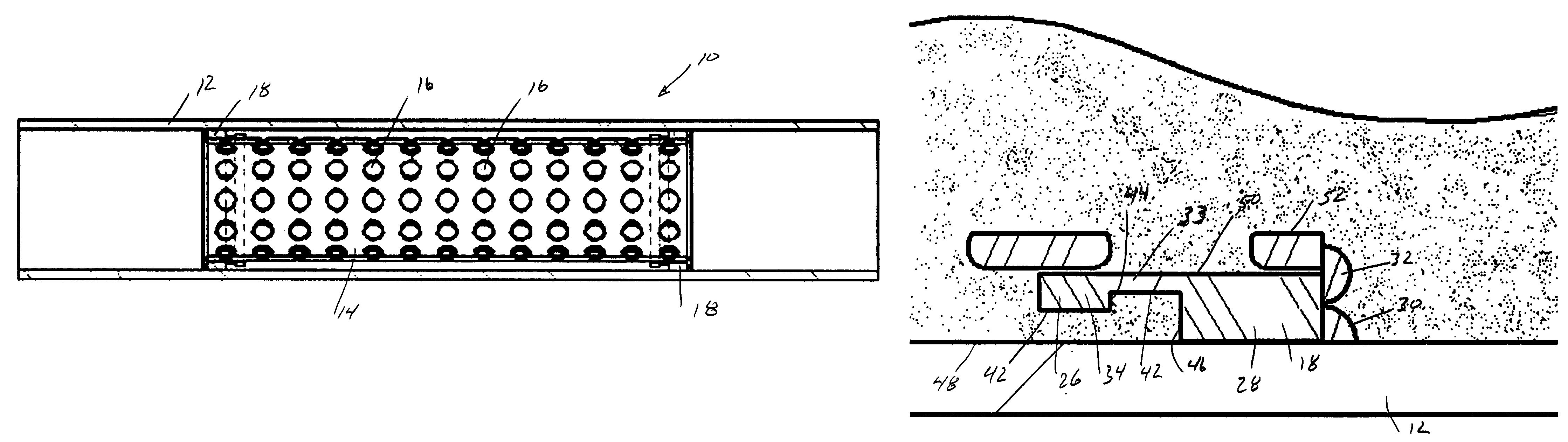
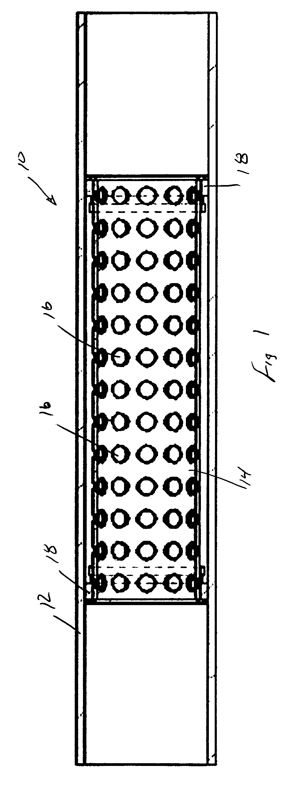
[0023]FIG. 1 discloses a progressing cavity pump or motor 10 having an outer sleeve-shaped tube 12 and an inner tube 14 spaced radially within the outer tube. The inner tube 14 includes a plurality of apertures 16, which may comprise a regular pattern of rows and columns as shown in FIG. 1. A pair of annular seal glands 18 are each secured to the inner surface of the inner tube and the outer surface of the outer tube, and position the inner tube when the elastomeric material of the stator is installed. Annular seal glands may be fixed at the desired locations along the axial length of the inner tube as needed to provide proper structural support. As explained subsequently, the annular seal glands provide a fluid seal between the stator and the outer tube. Although not shown in the figures, those skilled in the art will appreciate that the outer tube 10 and the housing discussed subsequently are conventionally threaded at the outer surface of their ends for attachment to conventional...


PUM


Abstract

A progressing cavity pump or a motor includes, in one embodiment, an outer tube 12, an inner tube 14, and a plurality of apertures 16. A pair of annular seal glands 18 seal the stator material to the outer tube. The stator material is injection molded into the inner tube and passes through the plurality of apertures and into an annular gap between the inner tube and the outer tube. In other embodiments, the outer housing for a progressing cavity pump or motor is provided with one or more grooves, with each groove having an outer surface radius less than the outer housing surface radius. A plurality of apertures are provided in fluid communication with the grooves. According to the method of the invention, the stator material is injected into the apertures and fills a space radially outward of the apertures to bond the stator materiaal to the outer housing.

Description

FIELD OF THE INVENTION[0001]The present invention relates to a progressing cavity pump or motor. More particularly, this invention relates to an improved techniques for mechanically connecting the elastomeric stator with the outer tube or housing of the pump or motor.BACKGROUND OF THE INVENTION[0002]Progressing cavity pumps and motors have been used for decades in pumping and hydraulic motor applications. The typical assembly consists of a rigid rotor which resembles a screw having multiple leads. The rotor mates with a stator which has one additional lead cut on the interior of the stator. The differences in the leads form cavities between the rotor and the stator. These cavities continually progress from one end of the stator to the other when the rotor is turned. Operation of the pump is achieved by mechanically turning the rotor, while operation as a motor is achieved by forcing fluid into the end cavity to turn the rotor.[0003]A stator is conventionally an elastomeric or plasti...

Claims


Application Information

Patent Timeline
Patent Type & Authority Patents(United States)
IPC IPC(8): F01C1/10F03C2/00F04C18/00F04C2/107F04C15/00
CPCF04C15/0003F04C2/1075B29C45/14631F04C15/0019F04D29/00
Inventor GUIDRY, MICHAELVACLAVIK, ED
Owner ROBBINS & MYERS ENERGY SYST
Why Eureka
Try Eureka