
Photon Source

a photon source and source technology, applied in the field of photon sources, can solve the problems of difficult collection and guiding of emitted photons, cumbersome collection techniques, and inability to meet the requirements of high-efficiency photon sources, and achieve the effects of improving stability and durability of photon sources, facilitating cooling or heat, and beneficial to the efficiency of photon sources

Inactive Publication Date: 2007-12-06
UNIVERSITY OF MELBOURNE
View PDF1 Cites 12 Cited by
  • Summary
  • Abstract
  • Description
  • Claims
  • Application Information

AI Technical Summary

Benefits of technology

[0009] Because the material is bonded to the waveguide and / or the material is incorporated in the optical waveguide, the or each colour centre is coupled to the waveguide. Consequently the photon source according to embodiments of the first and second aspect of the present invention has the advantage that not necessarily further optical components are required to direct the emitted single photons to the waveguide.
[0010] The photon source may be relatively robust and small, may be integrated and typically is relatively easy to cool or heat. In addition, a close association of the or each colour centre with the waveguide is beneficial for the efficiency of the photon source as colour centres are often isotropic photon emitters. The coupling of the or each colour centre with the waveguide may also result in improved stability and durability of the photon source.
[0025] In specific embodiments of the first and second aspect of the present invention the material is positioned in a cavity which is located in the waveguide, typically in or adjacent a core region of the waveguide. The cavity typically is an optical cavity and may be partially hollow or may at least in part be filled with a material that has a different refractive index than the core region. In this case the photon emission of the or each colour centre may be less isotropic and photons may be preferentially emitted into an enhanced cavity mode. Consequently, the optical cavity may improve the efficiency of the photon source.
[0034] The material may comprise diamond crystals having the or each colour centre. The step of growing the material typically involves chemical vapour deposition (CVD). The step of growing may also comprise growing the material in the or each recess, for example at an edge associated with the or each recess. The inventors have observed that, dependent on the growth conditions, favourable growth of the material may occur at the or each edge associated with the or each recess. The or each edge typically is at or near the core region and therefore the or each recess has the advantage that the diamond crystals predominantly grow at or near the core region.
[0044] Because the material is bonded to and / or incorporated in the waveguide and the or each colour centre is coupled to the waveguide, the quantum key distribution system comprising the above-defined photon source may be of improved practicality and efficiency.

Problems solved by technology

However, the single photons are emitted isotropically, which makes the collection and guiding of the emitted photons very difficult.
Usually an objective lens, accurately aligned to a single colour centre, is used to collect the emitted photons, but optical losses at optical interfaces can be significant and this collection technique is generally cumbersome and not very robust.
Further, optical lenses are difficult to combine with integrated technology and also make cooling or heating of the device more difficult.

Method used


Image

  • Photon Source
  • Photon Source
  • Photon Source

Examples


Embodiment Construction

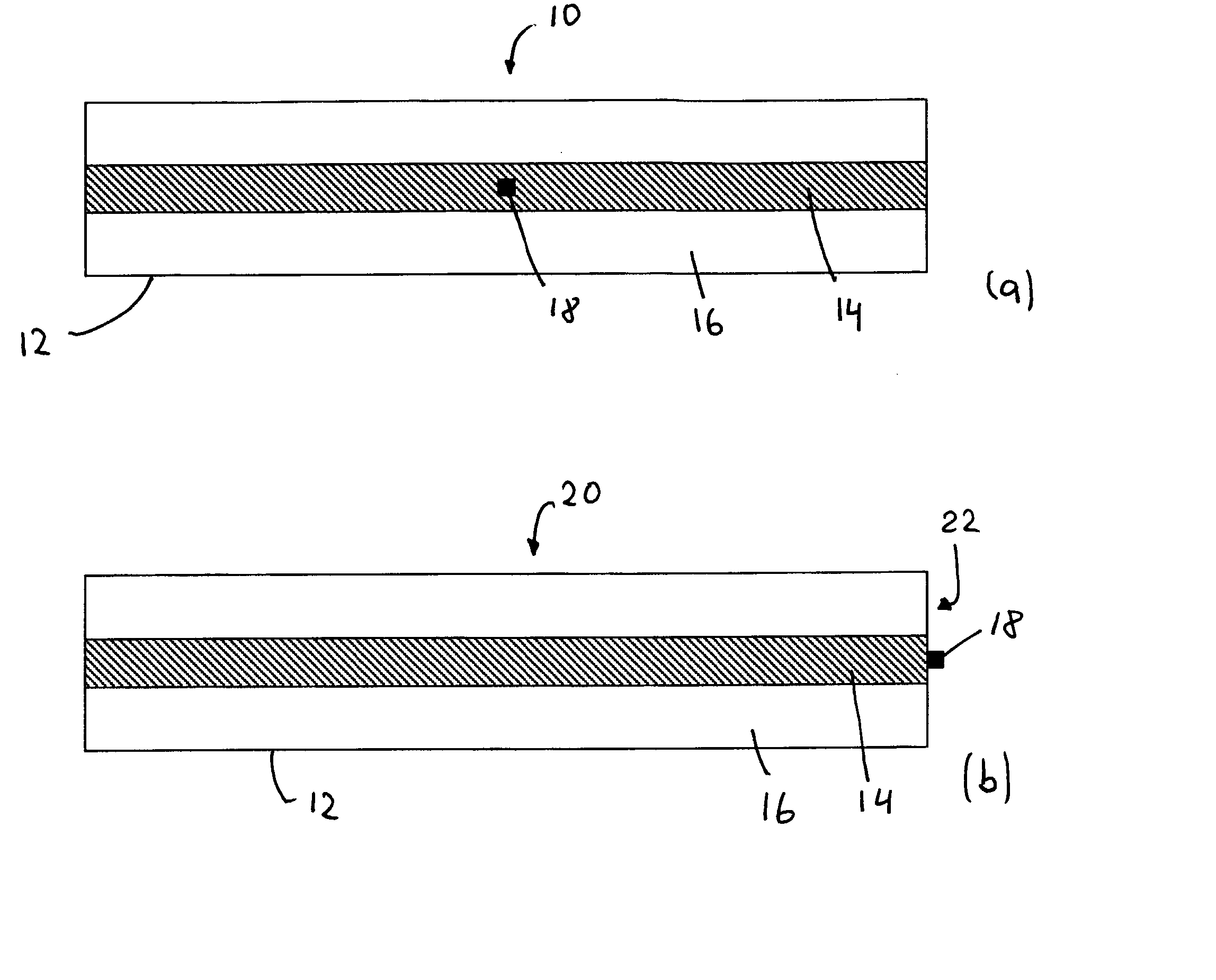
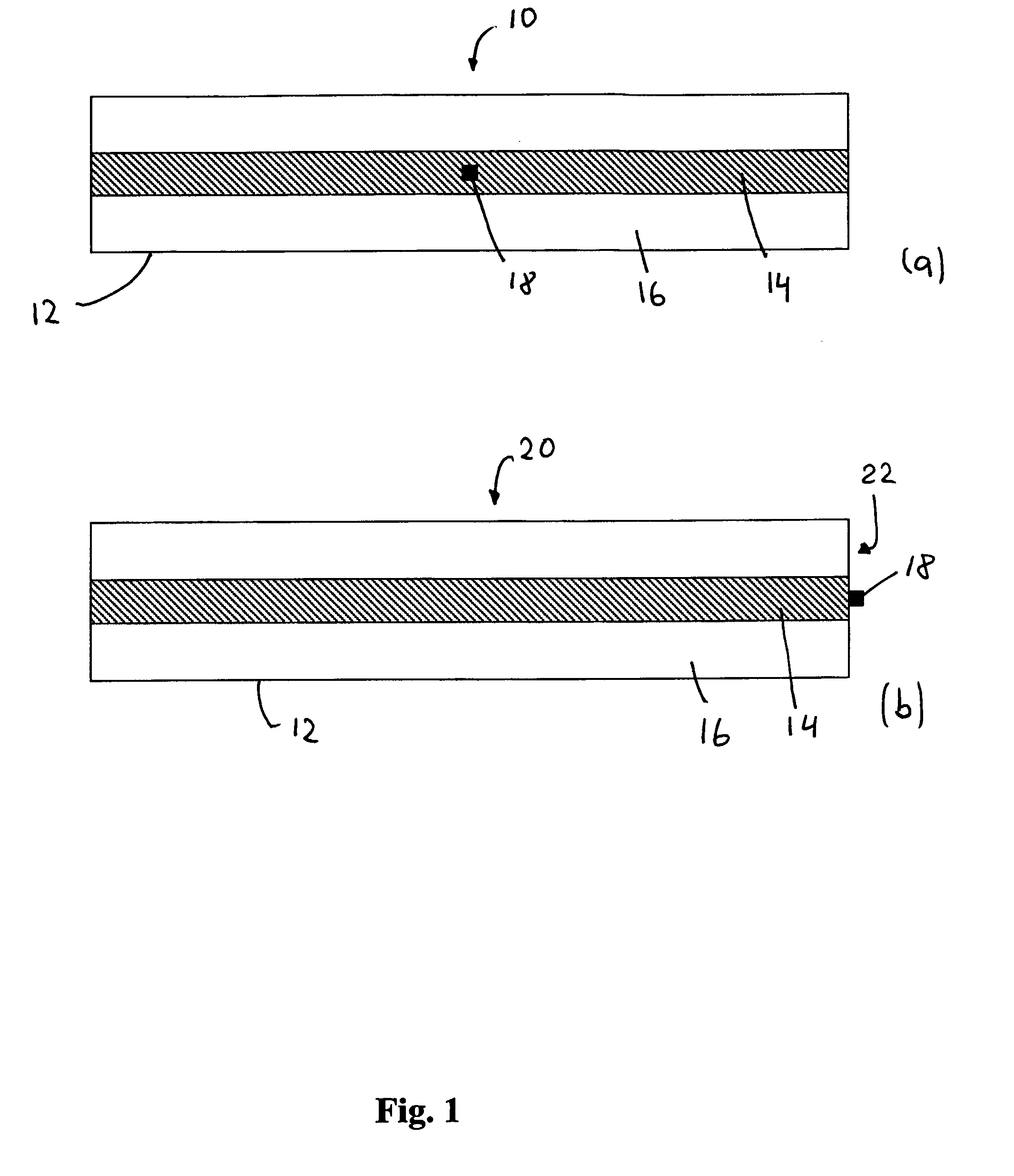
[0050] Referring initially to FIG. 1 (a), a photon source 10 according to a specific embodiment of the present invention is now described. The photon source 10 comprises an optical waveguide 12 having a core 14 and a cladding 16. In this embodiment the cladding 16 comprises a material that has a refractive index lower than that of the core 14. A diamond crystal 18 is embedded in the core 14. The diamond crystal 18 comprises a colour centre which in use emits single photons. In this embodiment, the colour centre comprises a vacancy in the lattice of the diamond crystal and an adjacent nitrogen atom that replaces another carbon atom so that a nitrogen-vacancy (NV) centre is formed. Laser radiation, for example having a wavelength of 514 nm or 532 nm, is used to excite the colour centre and the decay of the excited state results in the emission of a single photon.

[0051] It is to be appreciated that alternatively the photon source 10 may comprise any other suitable colour centre. In a ...


PUM

PropertyMeasurementUnit
wavelengthaaaaaaaaaa

Abstract

The present invention provides a photon source comprising an optical waveguide and a material having at least one colour centre. The or each colour centre is arranged for photon emission and the material is grown so that the material is bonded to the optical waveguide and in use at least some of the photons emitted by the or each colour centre are guided in the optical waveguide. The present invention also provides a photon source having an optical waveguide incorporating the material which has the at least one colour centre.

Description

FIELD OF THE INVENTION [0001] The present invention broadly relates to a photon source and relates particularly, though not exclusively, to a photon source suitable for quantum key distribution. BACKGROUND OF THE INVENTION [0002] For many applications, such as a quantum key distribution, photon sources are required that provide single photons or entangled multiple photons. Colour centres in diamond, for example, could be used for single photon emission. Such colour centres typically comprise at least one optically active impurity atom, such as a nitrogen atom, which is positioned adjacent to a vacancy in the diamond matrix. Such nitrogen-vacancy (N-V) centres are excited using an optical or electronic excitation source and are typically arranged to emit single photons having a wavelength in the vicinity of 637 nm. However, the single photons are emitted isotropically, which makes the collection and guiding of the emitted photons very difficult. Usually an objective lens, accurately ...

Claims


Application Information

Patent Timeline
Patent Type & Authority Applications(United States)
IPC IPC(8): G02F1/377H04L9/08G02F1/365
CPCH04L9/0852G02F1/365G02F1/335G02F1/39
Inventor RABEAU, JAMESHUNTINGTON, SHANE T.PRAWER, STEVENGREENTREE, ANDREW D.
Owner UNIVERSITY OF MELBOURNE
Learn More