
Planetary gearbox

a planetary gearbox and gearbox technology, applied in the direction of toothed gearings, transmission elements, drilling rods, etc., can solve the problems of increased wear, increased wear, and increased wear of inner toothing of the switching ring gear and the outer toothing of the web that is to be switched or blocked, so as to increase the switching process and increase the wear effect. , the effect of high speed differences

Inactive Publication Date: 2008-08-05
AEG ELECTRIC TOOLS
View PDF3 Cites 20 Cited by
  • Summary
  • Abstract
  • Description
  • Claims
  • Application Information

AI Technical Summary

Benefits of technology

"The present invention aims to improve the gearbox of a certain type by increasing its service life and reducing wear effects. This is achieved by adding a synchronization disk between the planet wheels and the outer toothing of the sleeve, which is entrained by the sleeve and acts frictionally on the switching ring gear or the planet wheels. The synchronization disk is designed to match the speed of the sleeve and outer toothing, and can be provided with a positive-locking drive and angled edge to improve friction engagement with the switching ring gear. The synchronization disk is particularly resistant to wear effects caused by the action of the ring gear toothing. The invention can be applied to a compact configuration with a multi-stage planetary gearbox."

Problems solved by technology

On the planetary gearbox of the power tools, usually an increased wear is observed during operation of the power tool and this wear is worsened even more by repeated shifting during operation when idling or operating under load.
Particularly the inner toothing of the switching ring gear and the outer toothing of the web that is to switched or blocked are subject to the wear effects.

Method used


Image

  • Planetary gearbox
  • Planetary gearbox
  • Planetary gearbox

Examples


Embodiment Construction

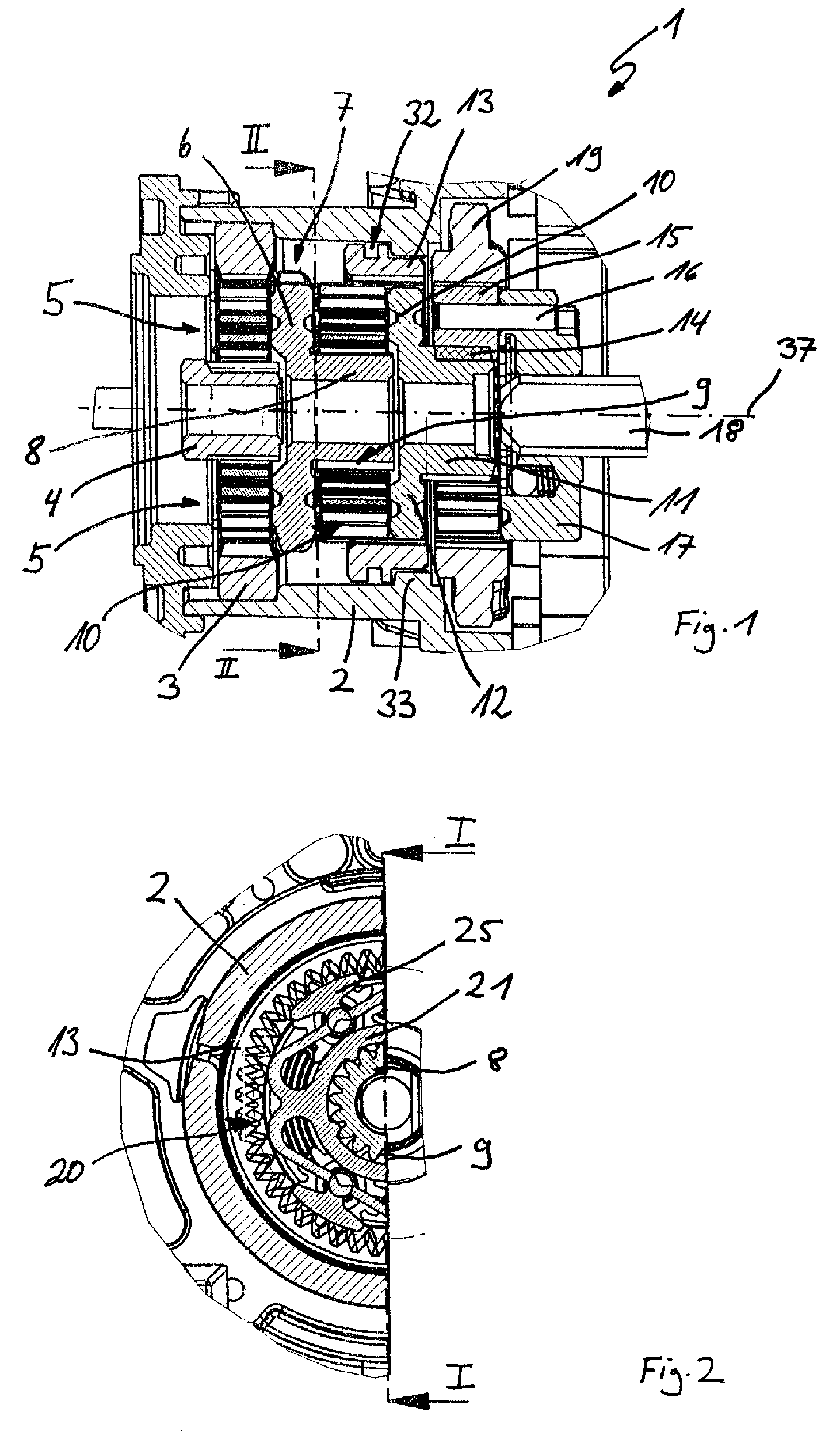
[0023]In the following description same parts are identified by same reference numerals.

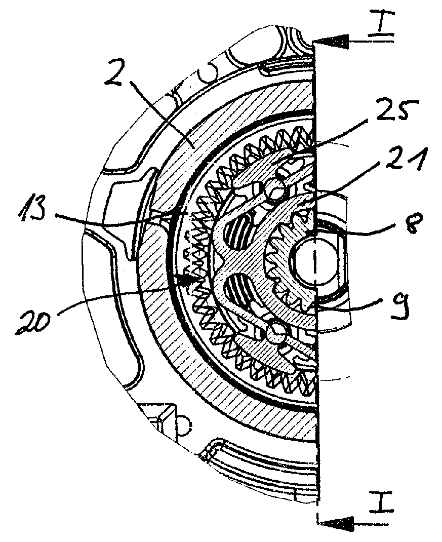
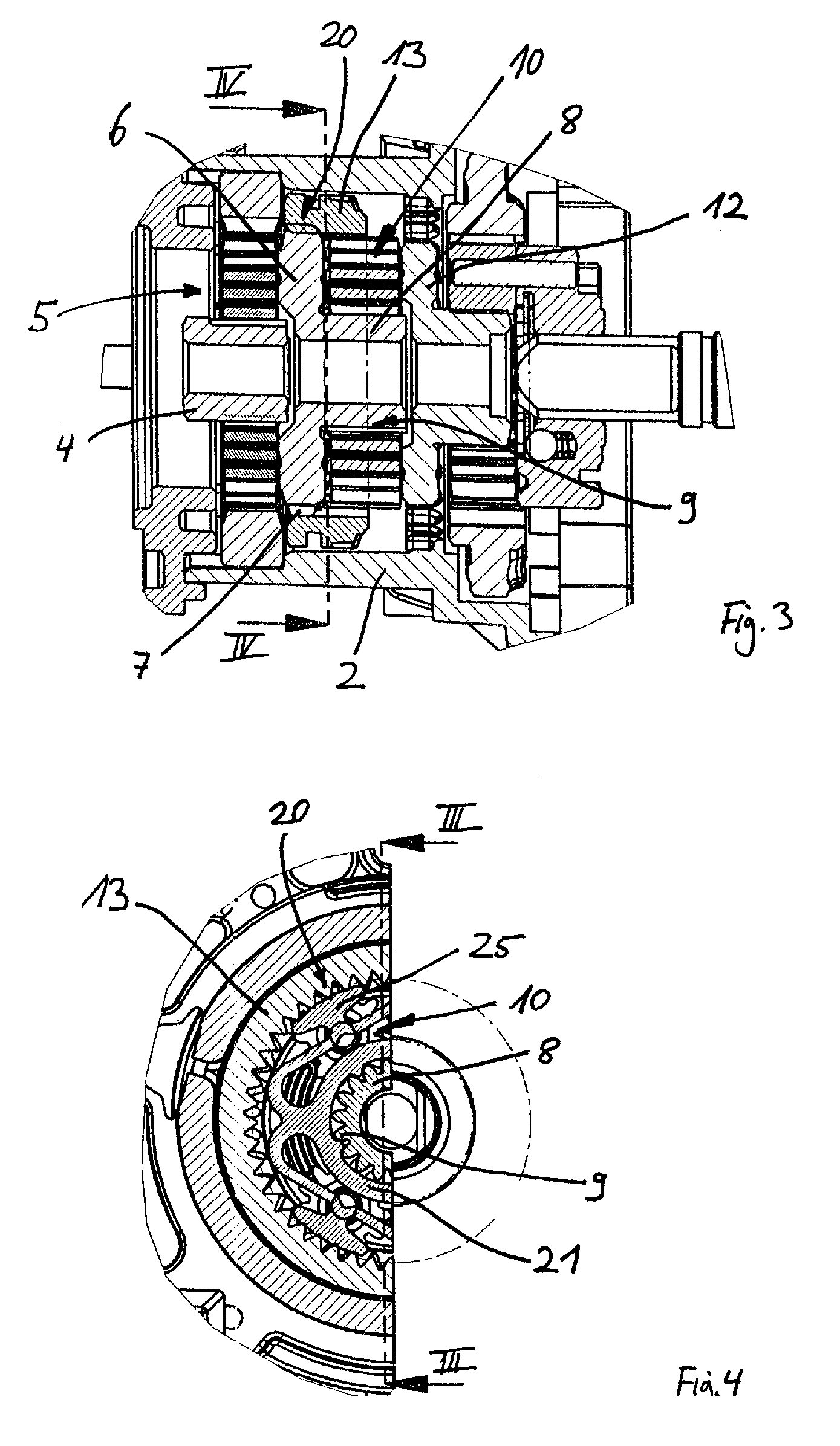
[0024]FIG. 1 shows a cross-section of a planetary gearbox 1 for a power tool, not illustrated, such as a power drill or the like, that is arranged between the drive motor of the power tool and its working spindle. The planetary gearbox 1 has in its housing 2 several gear stages that can be combined in different ways by a shifting device to be described in the following and, depending on the shifted position, transmit the speed of the motor at different transmission ratios onto the drive spindle and the tool of the power tool. The three gear stages are each designed as planetary gears and thus provide a favorable ratio between minimal size and transmittable power. The speed and the torque of the drive motor are introduced by a drive sleeve 4 into the gearbox 1 wherein the drive sleeve 4 is a central sun wheel of the first transmission stage. First planet wheels 5 are rolling on the sun wheel tooth...


PUM


Abstract

A planetary gearbox for a power tool has a planetary carrier and a rotatable sleeve with sun wheel toothing arranged centrally on the planetary carrier. The sleeve has a radial section with outer toothing. Planet wheels are positioned between planetary carrier and radial section and mesh with the sun wheel toothing. A switching ring gear surrounds the planet wheels and has an inner toothing meshing with the planet wheels. The switching ring gear is axiallay moveable on the planet wheels between first and second end positions for switching a transmission ratio. In the second end position the switching ring gear engages the outer toothing of the radial section. A synchronization disk, rotating with the rotary sleeve, is positioned between planet wheels and radial section and acts directly or indirectly by friction on the switching ring gear when the latter is moved from the first into the second end position.

Description

BACKGROUND OF THE INVENTION[0001]The invention relates to a switchable planetary gearbox, in particular, for a hand-held power tool, comprising a planetary carrier supporting on one end face several planet wheels whose toothing meshes permanently with a sun wheel toothing of a central rotary sleeve. The planetary gearbox further comprises a switching ring gear surrounding the planet wheels and meshing permanently with the toothing of the planet wheels. The switching ring gear is longitudinally slidable and, for switching a transmission stage of the planetary gearbox, can be moved into engagement with an outer circumferential toothing that is provided on the circumference of a radial section of the rotary sleeve covering the end face of the planet wheels facing away from the planetary carrier.[0002]As is known in the art, planetary gearboxes are comprised essentially of a central sun wheel on which the planet wheels supported on a planetary carrier are rolling. Usually three planet g...

Claims


Application Information

Patent Timeline
Patent Type & Authority Patents(United States)
IPC IPC(8): F16H3/44F16H3/78
CPCF16H3/66F16H3/78F16H2200/2064F16H2200/201F16H2200/0034
Inventor EISENHARDT, ARMIN
Owner AEG ELECTRIC TOOLS
Learn More