Error-detection flip-flop

a digital circuit and error detection technology, applied in error detection/correction, instruments, computing, etc., can solve problems such as delay in digital circuit change, inability to predict and account for circuit design, and inability to detect errors

Active Publication Date: 2008-08-05
TAHOE RES LTD
View PDF9 Cites 14 Cited by
  • Summary
  • Abstract
  • Description
  • Claims
  • Application Information

AI Technical Summary

Problems solved by technology

If, for some reason, the signal is delayed through this logic and does not arrive at the synchronizing element by the required time period, a timing error may result, which may impair operation of the digital circuit.
There are many variations, both static and dynamic, however, which cause delays to change in digital circuits.
Dynamic variations, such as reliability degradation, voltage and temperature fluctuations, and delay push-out due to crosstalk or noise, may be more difficult to predict and account for in a circuit design.
Margining is undesirable because the full benefit of the original circuit design, in terms of power efficiency and speed, is not realized.
Furthermore, margining does not always work.
As variations increase, the margins are increasing as well, resulting in lower performance or higher power demands.
In some circumstances, the variations may be difficult to accurately predict.
One technique employs double-sampling flip-flops to detect when an input signal to the flip-flop arrives late, causing an error.
If the later sampling does not match the original sampling, the data has arrived too late to be captured by the flip-flop, and an error is signaled.
The double-sampling technique involves a large amount of overhead in terms of clocking power and circuit area.

Method used


Image

  • Error-detection flip-flop
  • Error-detection flip-flop
  • Error-detection flip-flop

Examples


Embodiment Construction

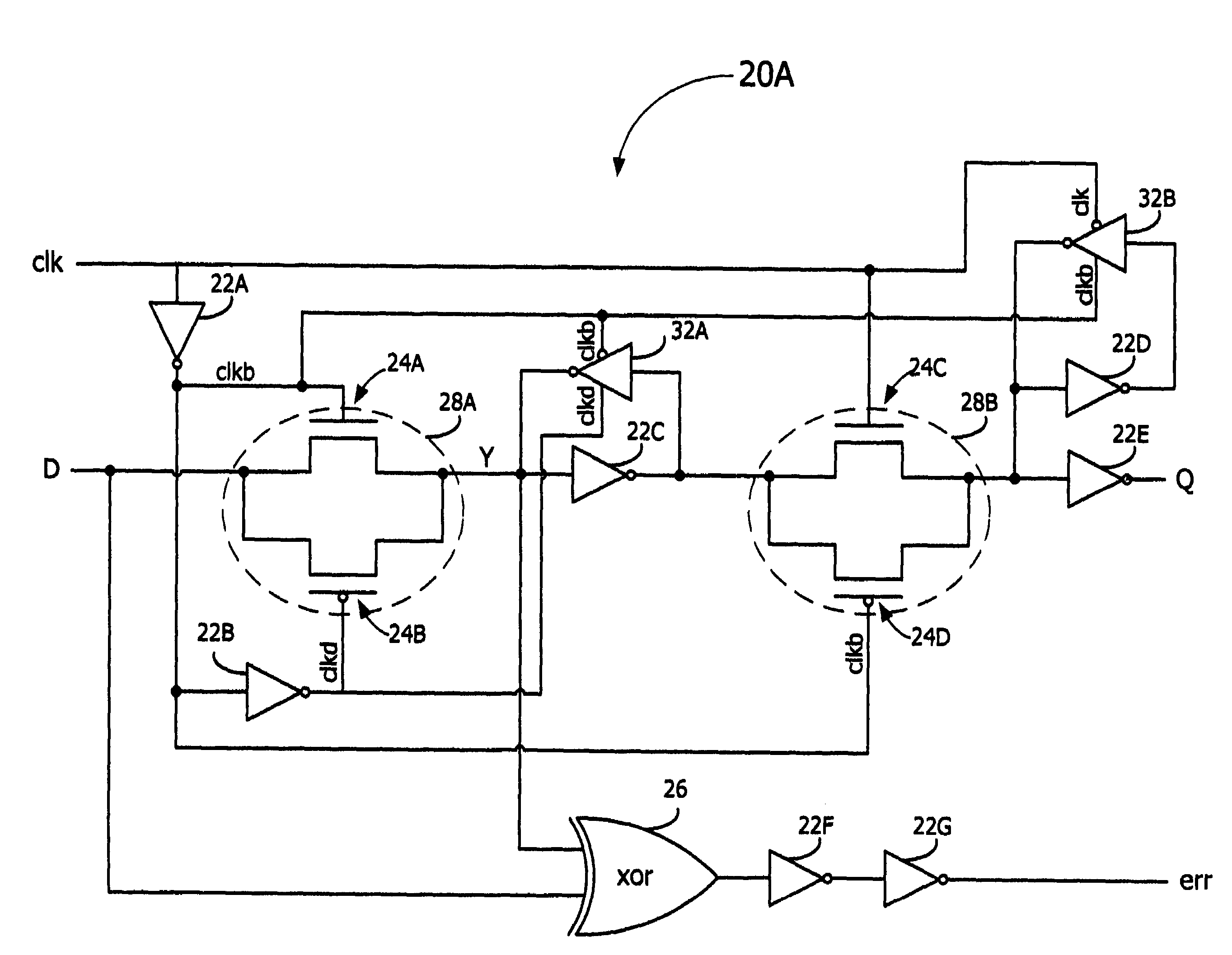
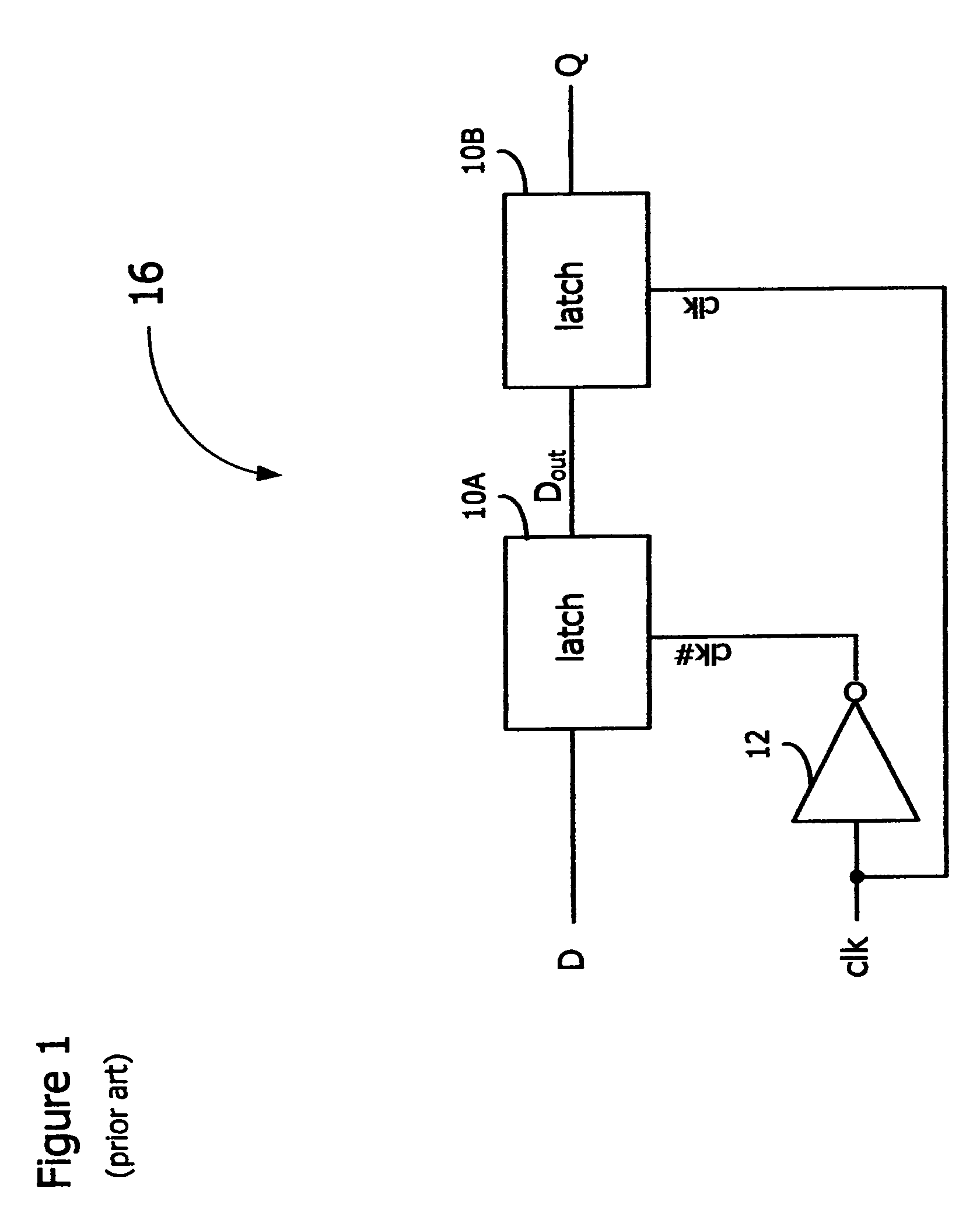
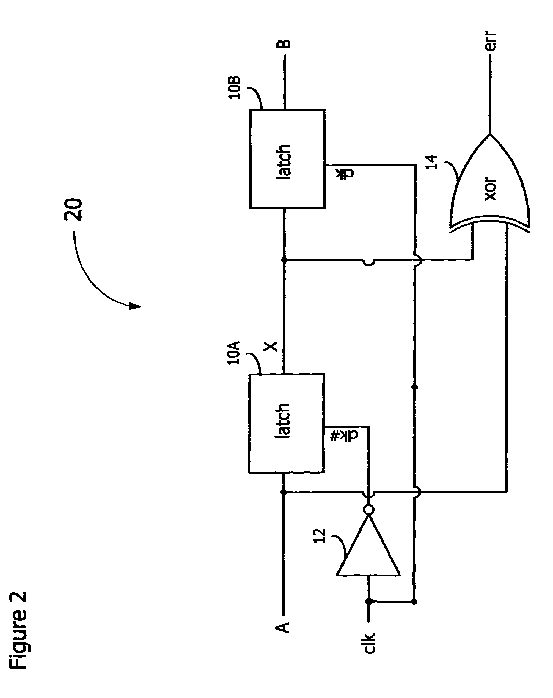
[0020]In accordance with the embodiments described herein, an error-detection flip-flop is disclosed for identifying timing errors in digital circuits. The error-detection flip-flop is a master-slave flip-flop including logic to determine whether an input signal is received during a predetermined portion of a clock period, signifying a timing error. The error-detection flip-flop produces a variable-length error pulse, which may be combined with other error pulses and converted to a stable signal for sampling by error-correction circuitry. Error-detection flip-flops may replace master-slave flip-flops in a digital circuit and yet do not increase the clocking power of the digital circuit and consume little additional circuit area.

[0021]In the following detailed description, reference is made to the accompanying drawings, which show by way of illustration specific embodiments in which the subject matter described herein may be practiced. However, it is to be understood that other embod...


PUM


Abstract

An error-detection flip-flop is disclosed for identifying timing errors in digital circuits. The error-detection flip-flop is a master-slave flip-flop including logic to determine whether an input signal is received during a predetermined clock period, signifying a timing error. The error-detection flip-flop produces a variable-length error pulse, which may be combined with other error pulses and converted to a stable signal for sampling by error-correction circuitry. The error-detection flip-flop does not increase the clocking power of the digital circuit and consumes little additional circuit area.

Description

TECHNICAL FIELD[0001]The application relates to timing errors in digital circuits and, more particularly, to error detection circuitry for digital circuits.BACKGROUND[0002]Digital circuits include circuit elements whose input signals are synchronized using one or more clocks. Between these synchronizing elements may be multiple stages of logic that perform the desired computation. The propagation delay of a signal through this logic must meet certain requirements such that the synchronizing elements are able to capture the correct data at the intended clock stage, e.g., the rising or falling edge of the clock. If, for some reason, the signal is delayed through this logic and does not arrive at the synchronizing element by the required time period, a timing error may result, which may impair operation of the digital circuit.[0003]Where the delay is known, the digital circuit may be designed to incorporate the delay. There are many variations, both static and dynamic, however, which c...

Claims


Application Information

Patent Timeline
Patent Type & Authority Patents(United States)
IPC IPC(8): G06F11/00G01R31/28
CPCG01R31/31937G01R31/31726
Inventor TSCHANZ, JAMESMITRA, SUBHASISHDE, VIVEK
Owner TAHOE RES LTD
Why Eureka
Try Eureka