Power tool anti-kickback system with rotational rate sensor

a technology of rotational rate sensor and power tool, which is applied in the direction of portable power-driven tools, manufacturing tools, metal sawing accessories, etc., can solve the problems of sudden impending kickback condition of power tools, rapid rise of output rapid increase of torque as the drill tries to break free, so as to avoid undesirable rotation of the power tool

Active Publication Date: 2008-08-12
BLACK & DECKER INC
View PDF47 Cites 113 Cited by
  • Summary
  • Abstract
  • Description
  • Claims
  • Application Information

AI Technical Summary

Benefits of technology

[0008]In another aspect of the present invention, the control scheme employed by the power tool may initiate different protective operations for different tool conditions.
[0010]In yet another aspect of the present invention, the control scheme employed by the power tool may initiate protective operations based on the rotational energy experienced by the tool.

Problems solved by technology

Generally speaking, all of these power tools may suddenly encounter an impending kickback condition at which time the output torque rapidly rises because of local changes in workpiece hardness, workpiece binding, tool obstruction from burrs and so forth.
These burrs can engage the flutes of the drill bit, thereby causing a rapid increase in torque as the drill tries to break free.
In some instances, the burrs may stop drill bit rotation, thereby causing a strong reaction torque that is imparted to the tool operator as the motor turns the tool in the operator's grasp (rather than turning the drill bit).
This reaction is can be problematic if the operator is standing on a ladder and / or holding the tool over their head.

Method used


Image

  • Power tool anti-kickback system with rotational rate sensor
  • Power tool anti-kickback system with rotational rate sensor
  • Power tool anti-kickback system with rotational rate sensor

Examples


Embodiment Construction

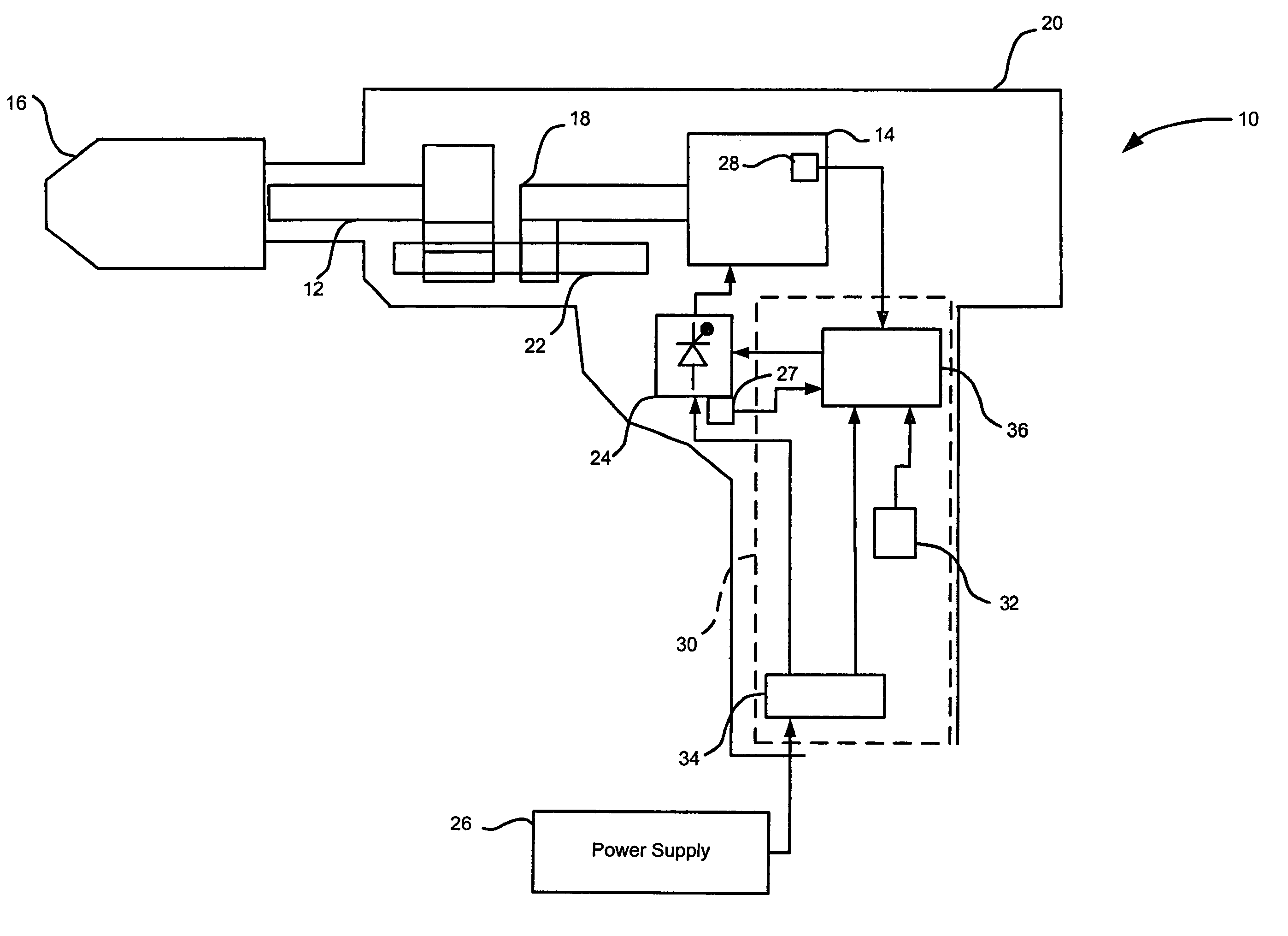
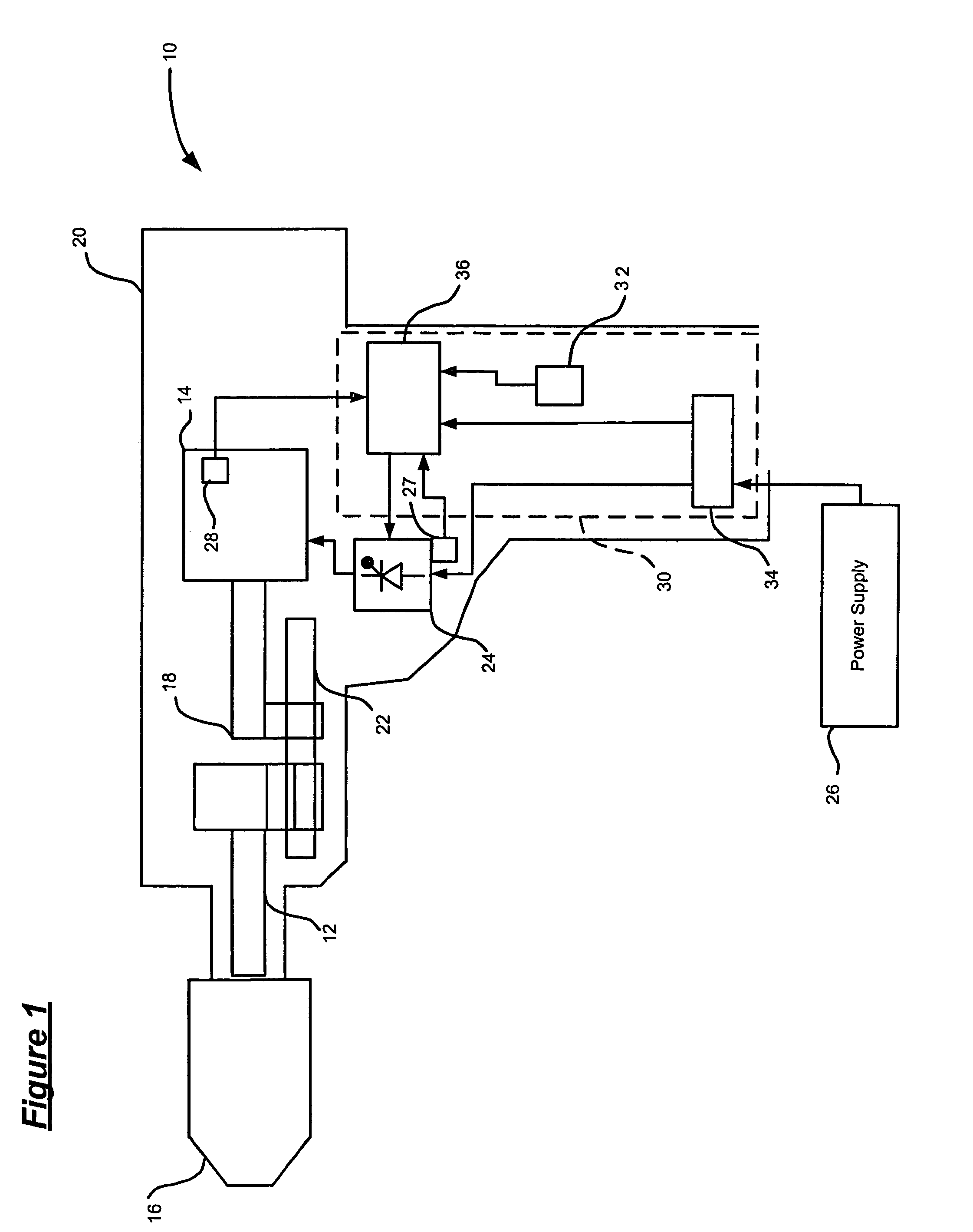
[0017]FIG. 1 illustrates an exemplary power tool 10 having a rotary shaft. In this example, the power tool is a hand held rotary hammer. While the following description is provided with reference to a rotary hammer, it is readily understood that the broader aspects of the present invention are applicable to other types of power tools having rotary shafts, such as drills.

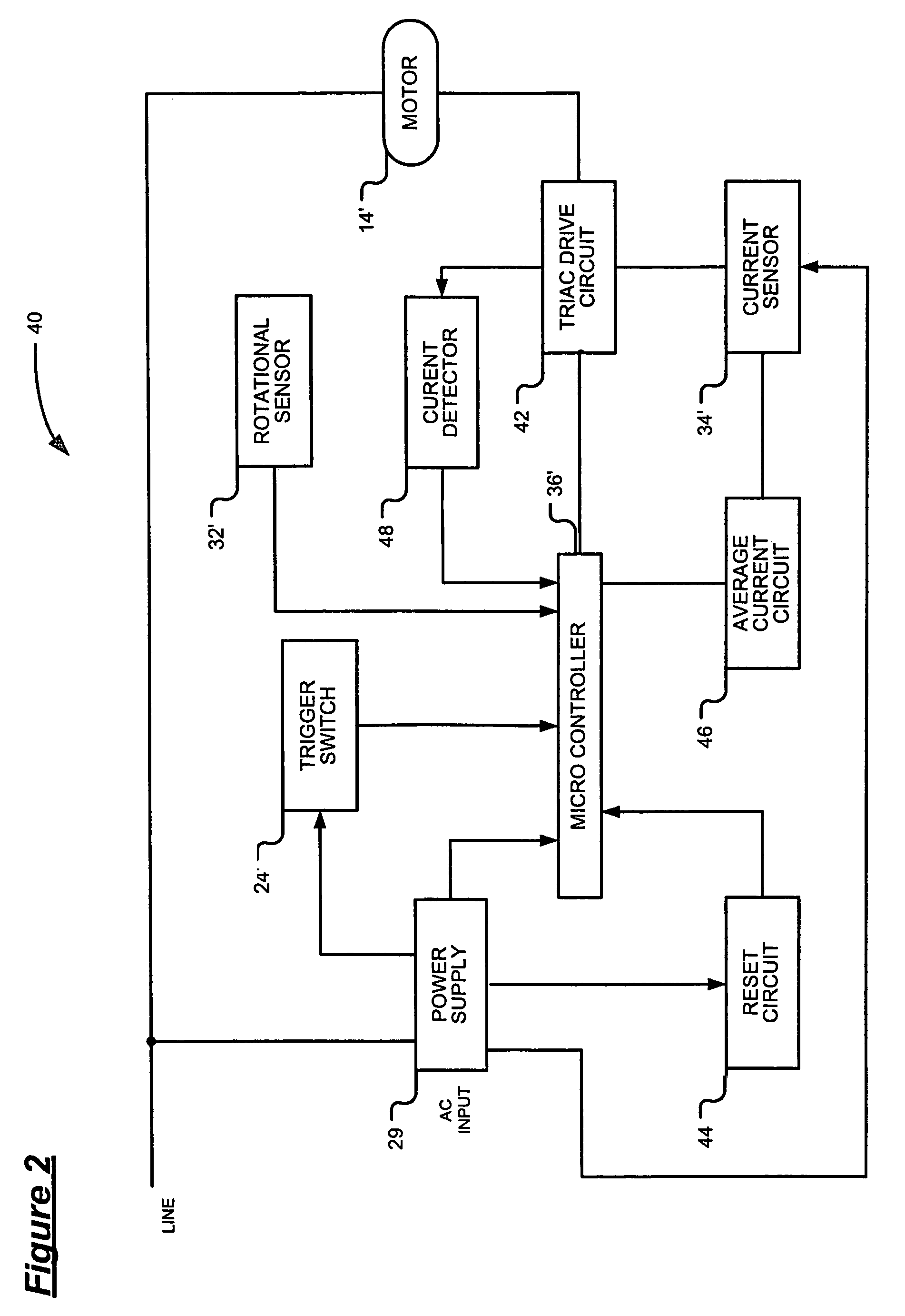
[0018]In general, the rotary hammer includes a spindle 12 (i.e., a rotary shaft) drivably coupled to an electric motor 14. A chuck 16 is coupled at one end of the spindle 12; whereas a drive shaft 18 of the electric motor 14 is connected via a transmission 22 to the other end of the spindle 12. These components are enclosed within a housing 18. Operation of the tool is controlled through the use an operator actuated switch 24 embedded in the handle of the tool. The switch regulates current flow from a power supply 26 to the motor 14. The power tool may further include a temperature sensor 27. Although a few primary c...


PUM

PropertyMeasurementUnit
rotational velocityaaaaaaaaaa
angular displacementaaaaaaaaaa
angular velocityaaaaaaaaaa

Abstract

A control system is provided for use in a power tool. The control system includes: a rotational rate sensor having a resonating mass and a controller electrically connected to the rotational rate sensor. The rotational rate sensor detects lateral displacement of the resonating mass and generates a signal indicative of the detected lateral displacement, such that the lateral displacement is directly proportional to a rotational speed at which the power tool rotates about an axis of the rotary shaft. Based on the generated signal, the controller initiates a protective operation to avoid further undesirable rotation of the power tool. The control scheme employed by the power tool may initiate different protective operations for different tool conditions.

Description

CROSS-REFERENCE TO RELATED APPLICATIONS[0001]This application claims the benefit of U.S. Provisional Application No. 60 / 620,283, filed on Oct. 20, 2004 and U.S. Provisional Application No. 60 / 675,692 filed on Apr. 28, 2005. The disclosure of the above applications are incorporated herein by reference.FIELD OF THE INVENTION[0002]The present invention relates generally to a safety mechanism for power tools and, more particularly, to a control system having a rotational rate sensor for detecting the onset of kickback condition in a power tool.BACKGROUND OF THE INVENTION[0003]Power tools typically employ a motor that imparts torque to a tool through a spindle. In the case of an electric drill, the motor spindle is coupled through a series of reducing gears to the chuck, which in turn holds the drill bit or other cutting / abrading tool, such as a hole saw, a grinding wheel or the like. Power screwdrivers as well a large rotary hammers work on a similar principle. In each of these cases, t...

Claims


Application Information

Patent Timeline
Patent Type & Authority Patents(United States)
IPC IPC(8): E21B15/04
CPCB23D59/001B25F5/00B25B21/00
Inventor ZHANG, QIANGDESHPANDE, UDAYWAIKAR, SHAILESH P.PUZIO, DANIELSCHELL, CRAIGHILSHER, WILLIAM F.WEST, JOSHUA D.
Owner BLACK & DECKER INC
Why Eureka
Try Eureka