
Waste water purification apparatus and waste water purification method including the regeneration of used coagulant

a technology of waste water purification and waste water purification method, which is applied in the direction of energy-based wastewater treatment, water treatment water, and centrifugal force sediment separation. it can solve the problems of increasing operation cost, increasing personnel cost, and increasing operation cost. it can also solve the problem of pollutant matter contamination and other problems, to achieve the effect of disinfecting pollutant matters

Inactive Publication Date: 2008-08-12
HITACHI LTD
View PDF7 Cites 16 Cited by
  • Summary
  • Abstract
  • Description
  • Claims
  • Application Information

AI Technical Summary

Benefits of technology

[0014]An object of the present invention is to provide a purification apparatus and an operation method therefor, which can regenerate and reuse the coagulant without resupplying the full quantity of an acid / alkali solution, and to provide a purification apparatus and an operation method therefor, which can recover oil from the recovered sludge and disinfect the pollutant matters.

Problems solved by technology

However, the coagulants are expensive, thereby causing increase in operation cost, and furthermore, the operators have to convey and resupply the coagulant at regular intervals which poses a problem that the operation cost is increased by the personnel cost to be increased accordingly.
In the above described treatment method, in order to regenerate coagulants an acid agent or an alkali agent is needed to be continuously added as expendable, and hence there has occurred a problem that the operation cost is increased by the cost defrayed for these two types of reagents and by the personnel cost defrayed for the labor of the periodic supply of these two types of reagents.
Further, in the case where the pollutant is crude oil, there occurs a problem that the floc disintegration by acid or alkali treatment alone allows the pollutant to remain mixed in the sludge so that the pollutant cannot be separated the from the sludge, and the regenerated coagulant is made to be mixed with the crude oil so that the coagulant cannot work as a satisfactory coagulant.
Furthermore, in the case where a purification apparatus is used on the sea-based platform for an offshore oil field, there occurs a problem that the periodic supply of the coagulant requires the transportation by a helicopter or a devoted ship, which is accompanied by a high transportation cost and a high unloading cost, thus resulting in an increase of the purification operation cost.
Moreover, in the case where are removed the pollutant matters such as the oil in the ballast water (For establishing the balance of a ship after unloading, sea water is filled in the vacant space in the ship, and the sea water is discharged into the sea immediately before loading.) in a crude oil tanker, a natural gas carrying vessel, an ore carrying vessel, or the like, and the bacteria, plankton and the like in the loaded sea water, periodic resupply of coagulants requires the purchase of chemicals at the anchoring sites, and is accompanied with a problem that the chemicals to be used are not easily obtainable depending on the anchoring sites.
Further, there occurs a problem that harmful plankton in the separated or removed / recovered sludge cannot be disinfected as the sludge remain separated so that the sludge is needed to be disinfected.
Further, in the case where a volume reduction apparatus is needed to be installed for the recovered sludge, the installation space has to be secured, with an accompanying problem of acquiring the space aboard.

Method used


Image

  • Waste water purification apparatus and waste water purification method including the regeneration of used coagulant
  • Waste water purification apparatus and waste water purification method including the regeneration of used coagulant
  • Waste water purification apparatus and waste water purification method including the regeneration of used coagulant

Examples


Embodiment Construction

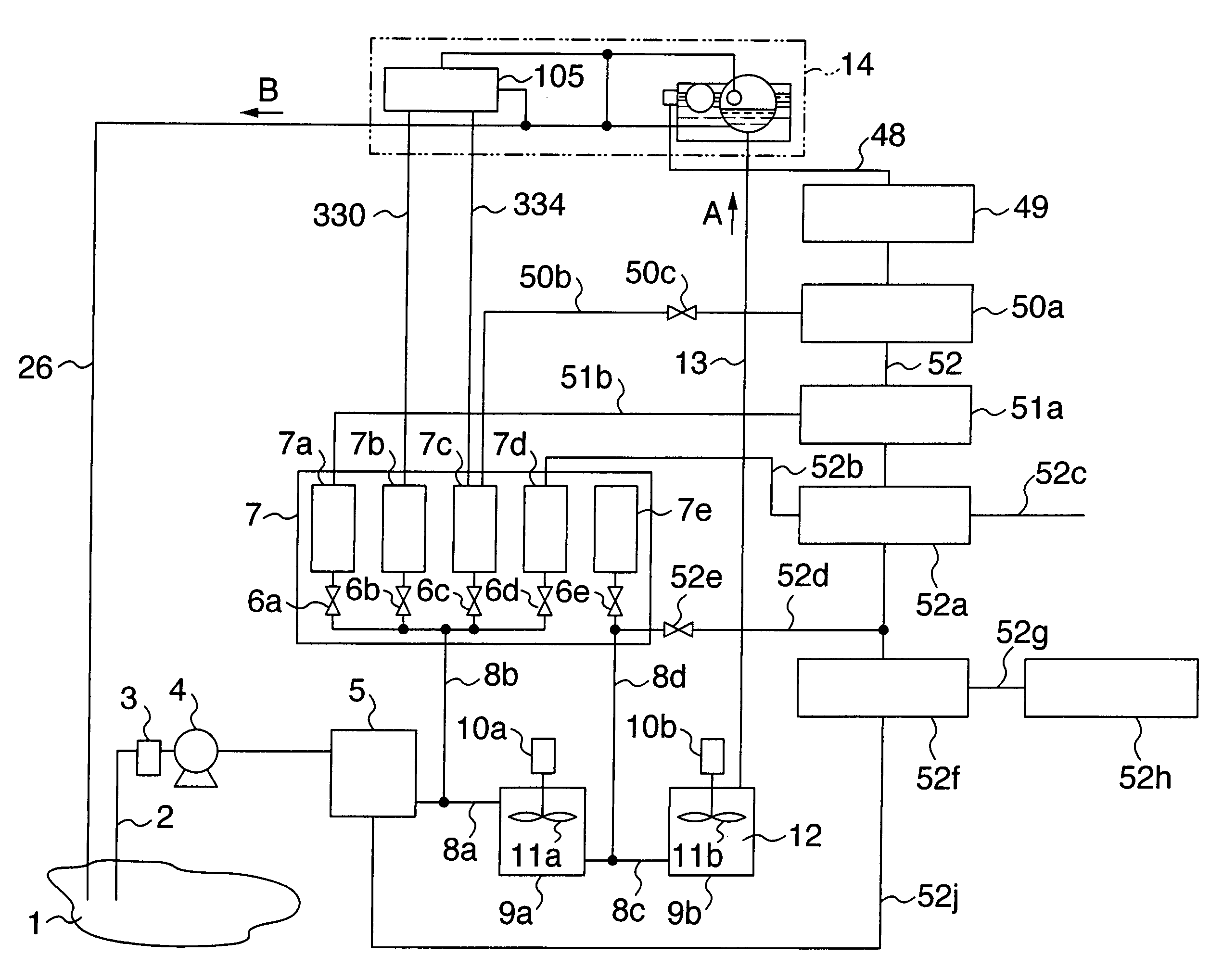
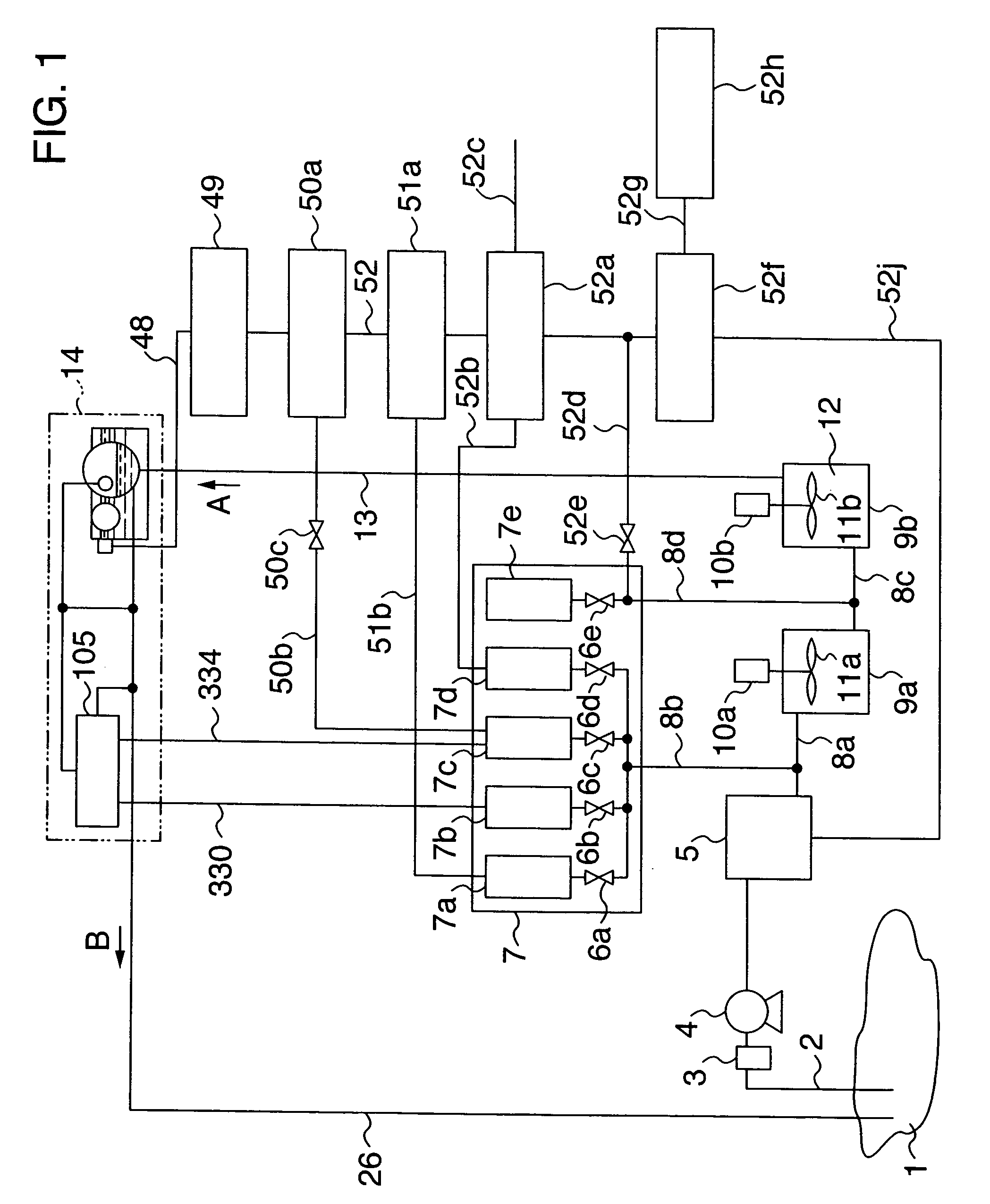
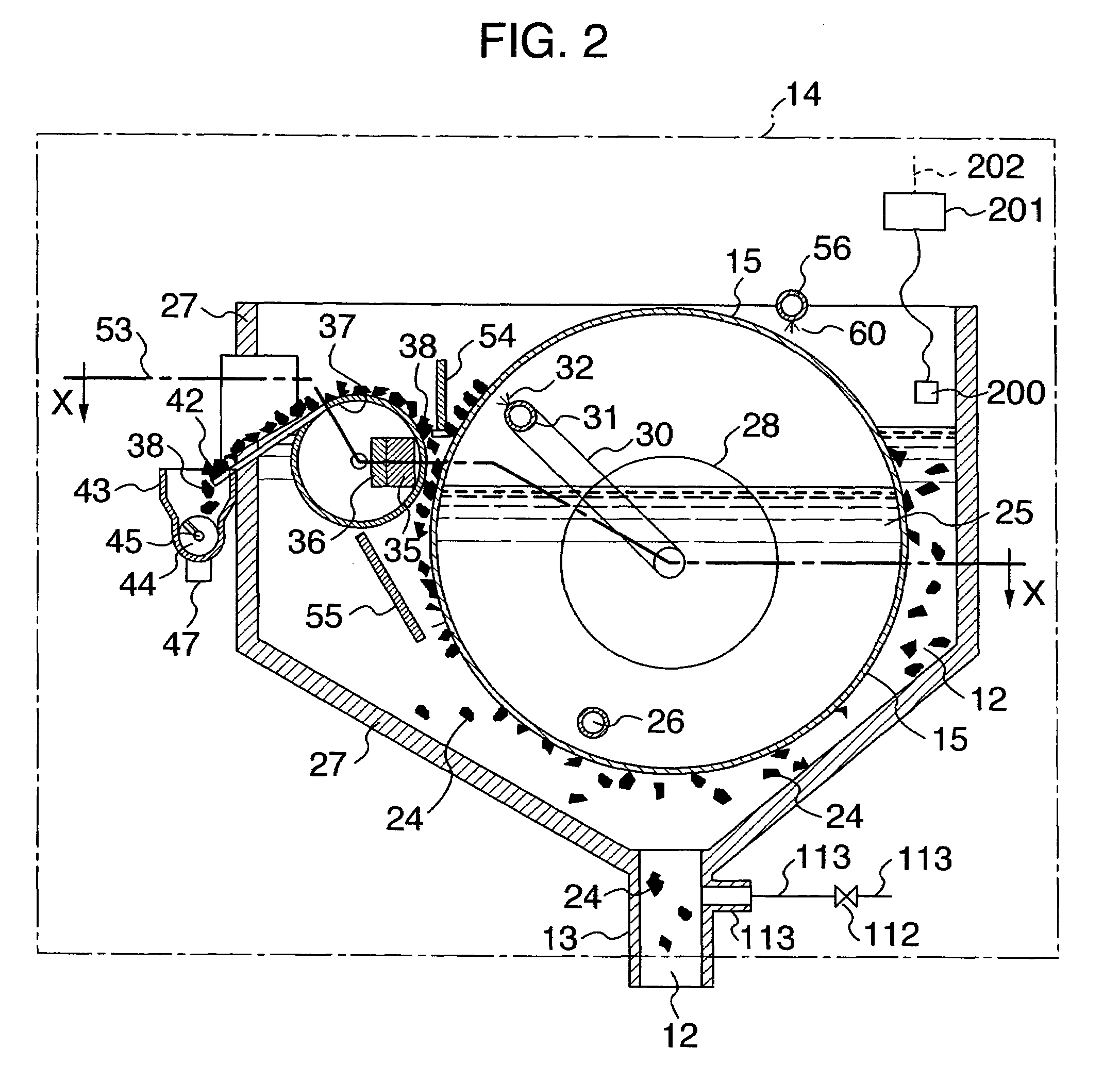
[0036]An embodiment of the invention will be described below with reference to FIGS. 1 to 3. FIG. 1 is a flow diagram of a waste water purification system in which the invention has been incorporated. FIG. 2 is an enlarged sectional view of the membrane separation apparatus shown in FIG. 1. FIG. 3 is a semi-sectional view of FIG. 2 as viewed from above.

[0037]In FIG. 1, the raw water of polluted sea water containing the pollutant matter including oil particles, bacteria, plankton, and organic matter particulates, all forming the matter to be removed, is drawn up into a raw water storage tank 5 from the sea 1 by use of a pump 4 through a duct 2 and a filter 3 for removing large pieces of trash. Into the raw water tank 5 are added a magnetic powder from a magnetic powder slurry tank 7a that supplies an magnetic powder of triiron tetraoxide slurry, a pH adjusting agent either from a sodium hydroxide aqueous solution tank 7b that supplies an alkaline pH adjusting agent containing sodium ...


PUM

PropertyMeasurementUnit
magneticaaaaaaaaaa
particle sizeaaaaaaaaaa
specific gravityaaaaaaaaaa

Abstract

A waste water purification system for purifying polluted salt water including oil and the like by coagulating and separating pollutant matter in the polluted salt water can regenerate and reuse a coagulant in the system while scarcely resupplying the coagulant, an acid solution and an alkaline solution. The acid and alkaline solutions are required for disintegrating coagulated flocs from the polluted salt water and regenerating the coagulant from sludge. Alkaline water enriched in sodium hydroxide and an acidic aqueous solution containing hydrochloric acid and the like are generated by electrolyzing the purified salt water. The flocs in the separated sludge are disintegrated by use of the alkaline water, pollutant matter is removed from the disintegrated aqueous solution, and the strong acidic containing the hydrochloric acid is added to the aqueous solution removed of the pollutant matter to have the coagulant. The coagulant can be thus regenerated from the recovered sludge.

Description

TECHNICAL FIELD[0001]The present invention relates to a waste water purification apparatus and an operation method therefor, which can reuse coagulants in a recycling manner and can dispose of recovered sludge satisfactorily.BACKGROUND ART[0002]Existing apparatuses for purification of polluted water, for example, include purification apparatuses and operation methods in which for the purpose of filtering separation of pollutant particles of a few μm or more in particle size or separating them according to specific gravity differences, a coagulant capable of supplying aluminum ion or iron ion is added to the polluted water as pretreatment for separation treatment, so that the pollutant particles are collected in the flocs whose matrixes are aluminum hydroxide and iron hydroxide, to form large and dense pollutant particle clumps of a few hundreds to a few thousands μm in particle size such that polluted water is purified through separation based on filtration or specific gravity diffe...

Claims


Application Information

Patent Timeline
Patent Type & Authority Patents(United States)
IPC IPC(8): C02F1/00C02F1/48C02F1/52B63B13/00B01D33/06B01D35/06B03C1/28B63J4/00C02F1/38C02F1/44C02F1/46C02F1/461C02F1/463C02F1/56C02F1/66C02F9/00C02F11/12C02F11/14
CPCB03C1/284B03C1/286C02F1/4618C02F1/488C02F1/5245C02F9/00C02F2303/16C02F1/001C02F1/385C02F1/441C02F1/463C02F1/481C02F1/52C02F1/56C02F1/66C02F11/121C02F2001/46185C02F2101/105C02F2101/32C02F2103/008C02F2103/08C02F2201/008C02F2201/46165C02F2209/40C02F2209/42Y02W10/37Y02A20/131
Inventor SAHO, NORIHIDEISOGAMI, HISASHIASANO, KATSUHIKO
Owner HITACHI LTD
Learn More