
Pouch type secondary battery

a secondary battery and pouch technology, applied in the field of pouch casing secondary batteries, can solve the problems of short circuit poor protection of the battery, thin and thin layer of the electrode assembly, etc., and achieve the effects of reducing the change in external dimension, enhancing reliability and safety, and enhancing reliability

Inactive Publication Date: 2008-08-12
SAMSUNG SDI CO LTD
View PDF11 Cites 20 Cited by
  • Summary
  • Abstract
  • Description
  • Claims
  • Application Information

AI Technical Summary

Benefits of technology

The present invention provides a pouch type secondary battery with enhanced reliability and safety. The battery has reinforcement structures on the electrode assembly to protect it from external impacts. The battery also has a reduced change in external dimension due to volumetric expansion of the electrode assembly. The battery has a pouch cover with metal and insulated from the battery. The battery includes electrode pins that are electrically connected to the electrodes and the pouch cover. The battery may also have a reinforcement member and an insulating terminal cover for protection. The technical effects of the invention include improved reliability, safety, and reduced size of the battery.

Problems solved by technology

The above-described configuration is very thin and provides a poor protection for the electrode assembly housed in the pouch casing 20.
Also, the safety and reliability of the battery may be impaired if the related art pouch is disturbed.
If the thermal adhesion layer melts the Al metal film inside may be exposed, and thus creating short circuit of the electrode assembly.
Additionally, the separator sheets 13 may shrink compounding the problem.
The above-described battery pouches have several drawbacks including poor structural stability.
Also, a stacked electrode assembly may cause a short circuit between electrodes.

Method used


Image

  • Pouch type secondary battery
  • Pouch type secondary battery
  • Pouch type secondary battery

Examples


Embodiment Construction

[0052]Reference will now be made in detail to embodiments of the present invention, examples of which are illustrated in the accompanying drawings.

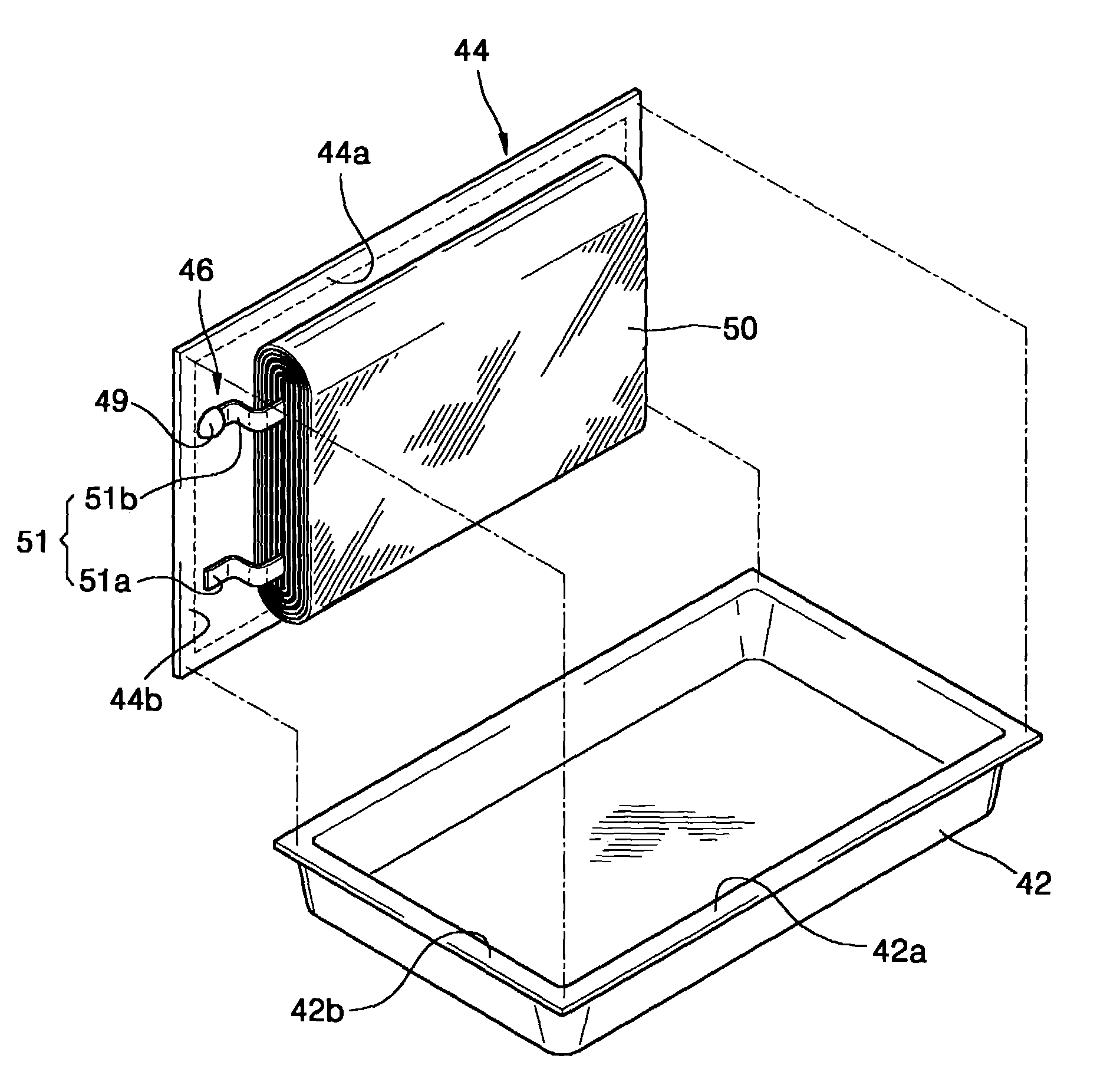
[0053]FIG. 4 illustrates a partially disassembled perspective view of a pouch type secondary battery according to an embodiment of the present invention. FIG. 5 illustrates a perspective view of a pouch type secondary battery according to an embodiment of the present invention. Referring to FIGS. 4 and 5, including an electrode assembly 50 having a first electrode plate and a second electrode plate with a separator interposed therebetween. A pouch casing 42 for housing the electrode assembly 50 and a pouch cover 44 is coupled to and sealed via a flange 42a. Of course other configurations can be used.

[0054]In one exemplary illustration, the electrode assembly 50 may be in the form of a roll. That is, the first electrode plate and the second electrode plate may have a separator interposed between the plates and the configuration is wound in...


PUM

PropertyMeasurementUnit
temperatureaaaaaaaaaa
melting pointaaaaaaaaaa

Abstract

A battery has enhanced reliability by protecting the battery from external impacts by separately installing a reinforcement structure on a casing and an electrode assembly housed in the casing. The configuration reduces or minimizes volumetric change in the dimensions due to volumetric expansion of the electrode assembly. The battery may include an electrode assembly having first and second electrode plates with a separator interposed therebetween. First and second terminal portions extending from the first and second electrode plates and a pouch casing having an open portion and for housing the electrode assembly. A pouch cover coupled and sealed with an opening of the pouch casing. The pouch cover having at least one throughhole and at least one electrode pin fastened to the throughhole. The electrode pin is electrically connected to one of the first and second terminal portions of the electrode assembly. The first and second leads are exposed outside the pouch cover and are electrically connected to the first and second terminal portions.

Description

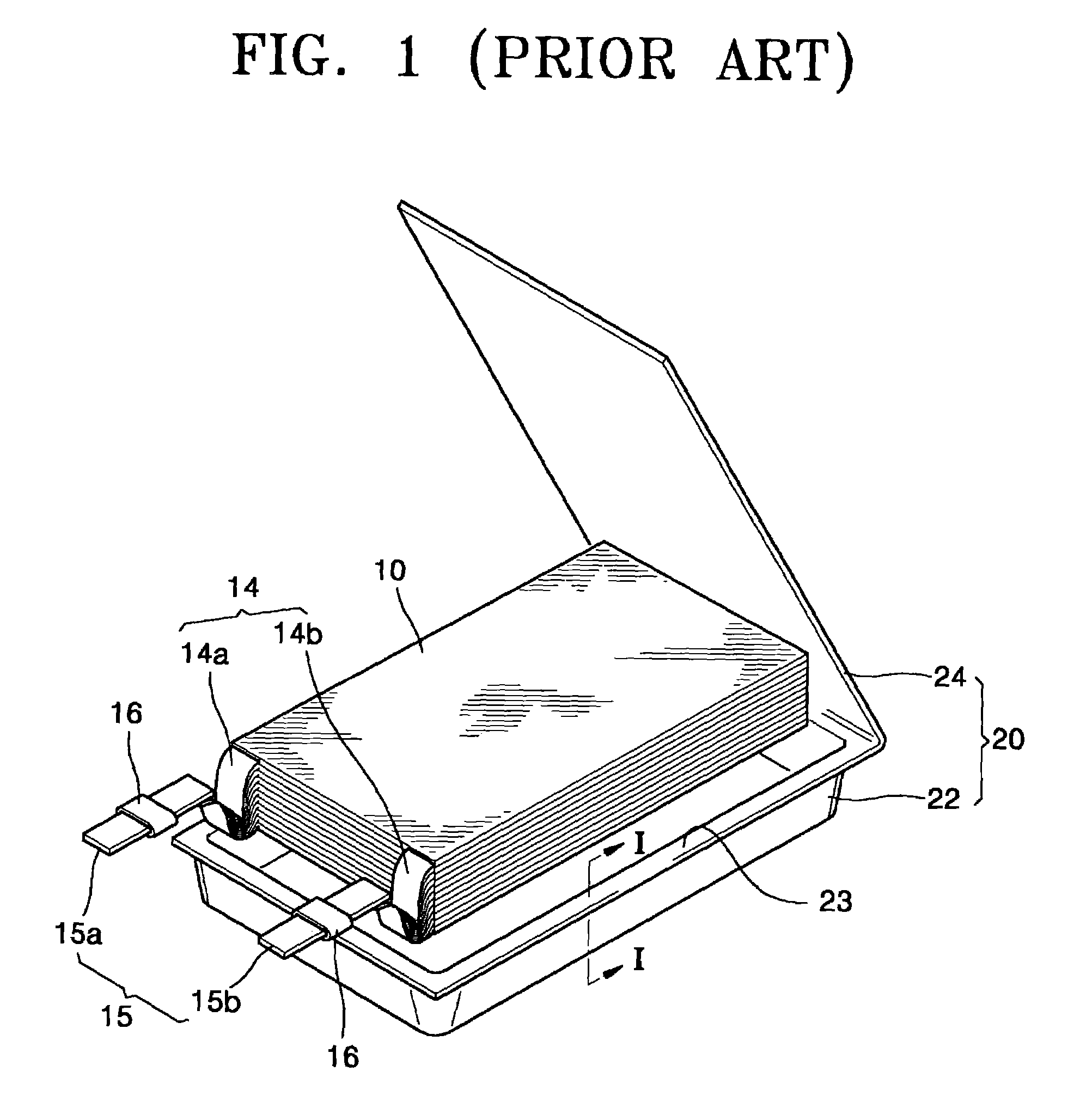
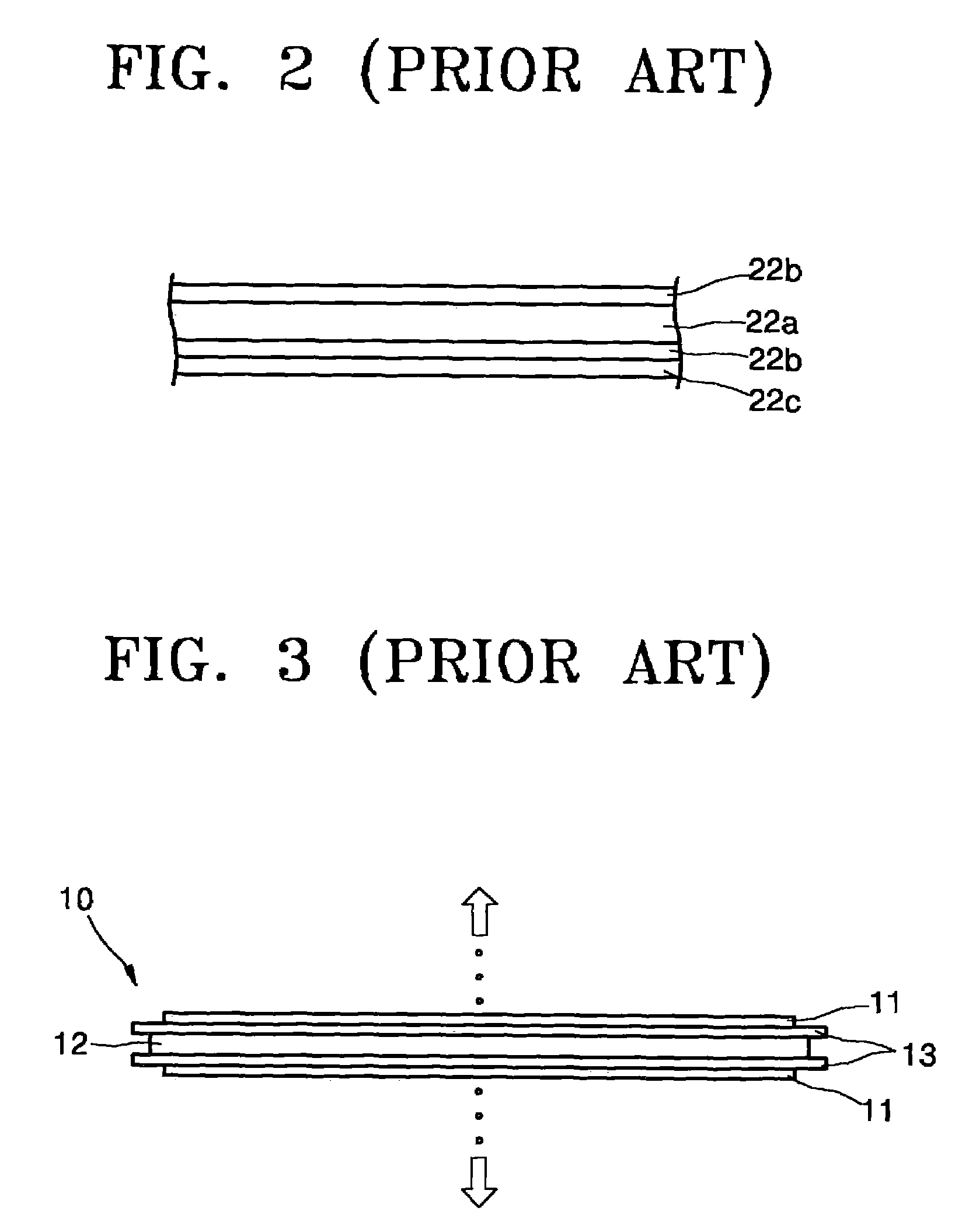
BACKGROUND OF THE INVENTION[0001]1. Field of the Invention[0002]The present invention relates to a battery, and more particularly, to a secondary battery with a pouch casing having an improved reinforcement structure.[0003]2. Discussion of the Related Art[0004]Rechargeable secondary batteries are typically small in size and have a large storage capacity. Some examples of the batteries include nickel-metal hydride (Ni—MH) and lithium (Li) ion batteries.[0005]Secondary batteries may be categorized as cylindrical, rectangular, and pouch type. The cylindrical batteries may use an aluminum can type structure, while the rectangular batteries typically use a rectangular aluminum can type structure. The pouch type batteries may be arranged in a thin film pouch casing.[0006]FIG. 1 is an extracted perspective view of a pouch type secondary battery according to the related art.[0007]Referring to FIG. 1, an electrode assembly 10 for generating a predetermined current and a pouch casing 20 for e...

Claims


Application Information

Patent Timeline
Patent Type & Authority Patents(United States)
IPC IPC(8): H01M2/04H01M2/26H01M50/178H01M50/55H01M50/557H01M50/567
CPCH01M2/021H01M2/06H01M2/0212Y02E60/10H01M50/557H01M50/567H01M50/55H01M50/178
Inventor KIM, SANG-BUMKIM, CHANG-HOCHANG, YOUN-HAN
Owner SAMSUNG SDI CO LTD
Learn More