
Apparatus and method for prioritized apportionment of transmission power in a multi-carrier terminal

Active Publication Date: 2008-08-12
QUALCOMM INC
View PDF24 Cites 155 Cited by
  • Summary
  • Abstract
  • Description
  • Claims
  • Application Information

AI Technical Summary

Benefits of technology

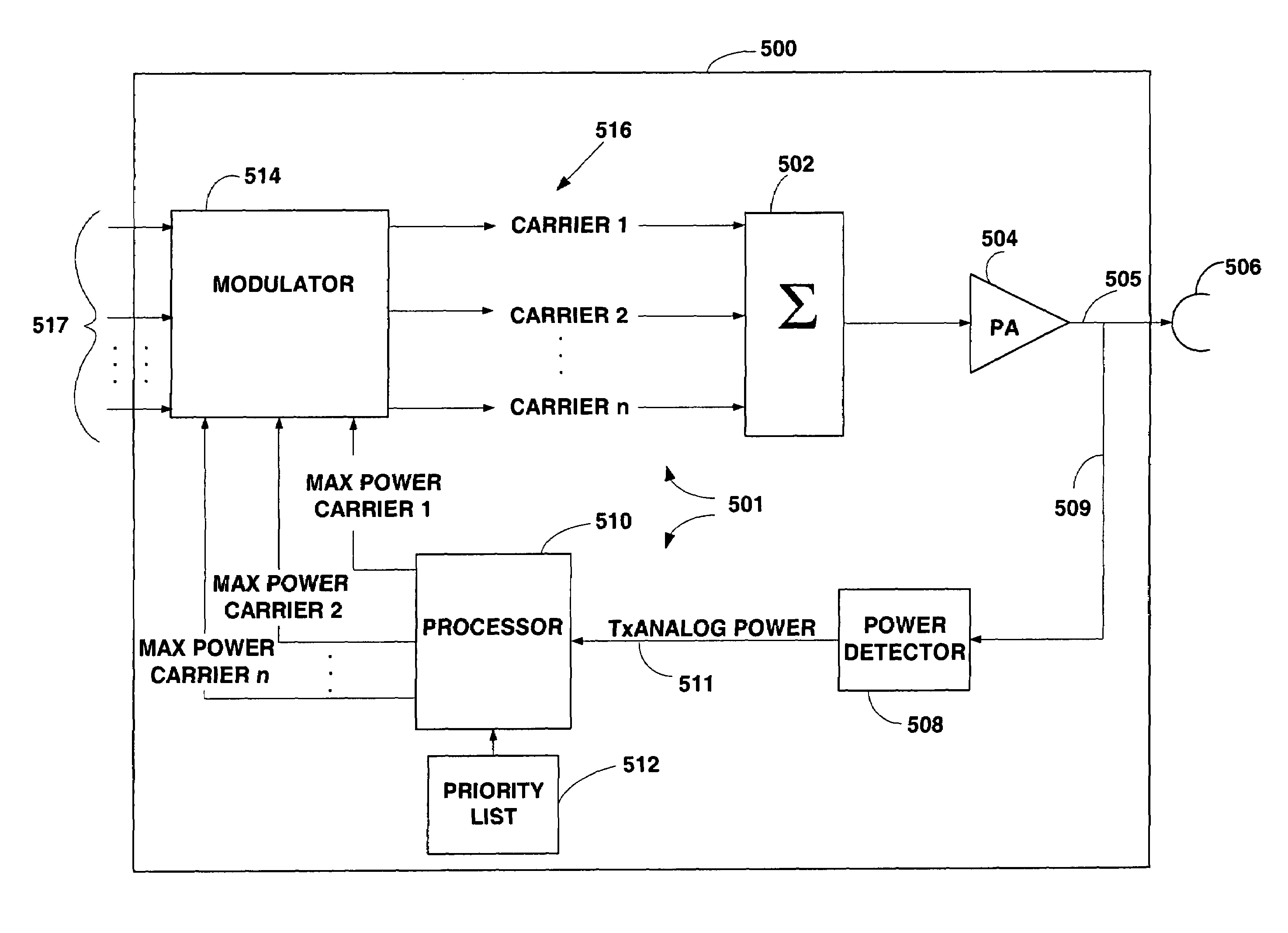
[0010]Embodiments disclosed herein address the above stated needs by assigning precedence to a first carrier of a multi-carrier transmitter with a plurality of carriers served by a single power amplifier and allocating transmission power subject to a limit to one or more other carriers according to whether or not the channel served by the first carrier is in an active state. This ensures that the first carrier will be able to utilize what it needs of the total available transmission power, up to the limit, and that the next carrier has available for its needs the total available transmission power less the total power used by the first carrier. This ordered apportioning of power may be employed for a plurality of carriers that use the power amplifier, with the next carrier in priority having available for its needs the total available transmission power less the total power used by all of the carriers preceding it in priority.

Problems solved by technology

However, limitations on space, manufacturing cost, power consumption and other factors dictate the need to share resources among the carriers, including power amplification circuitry.
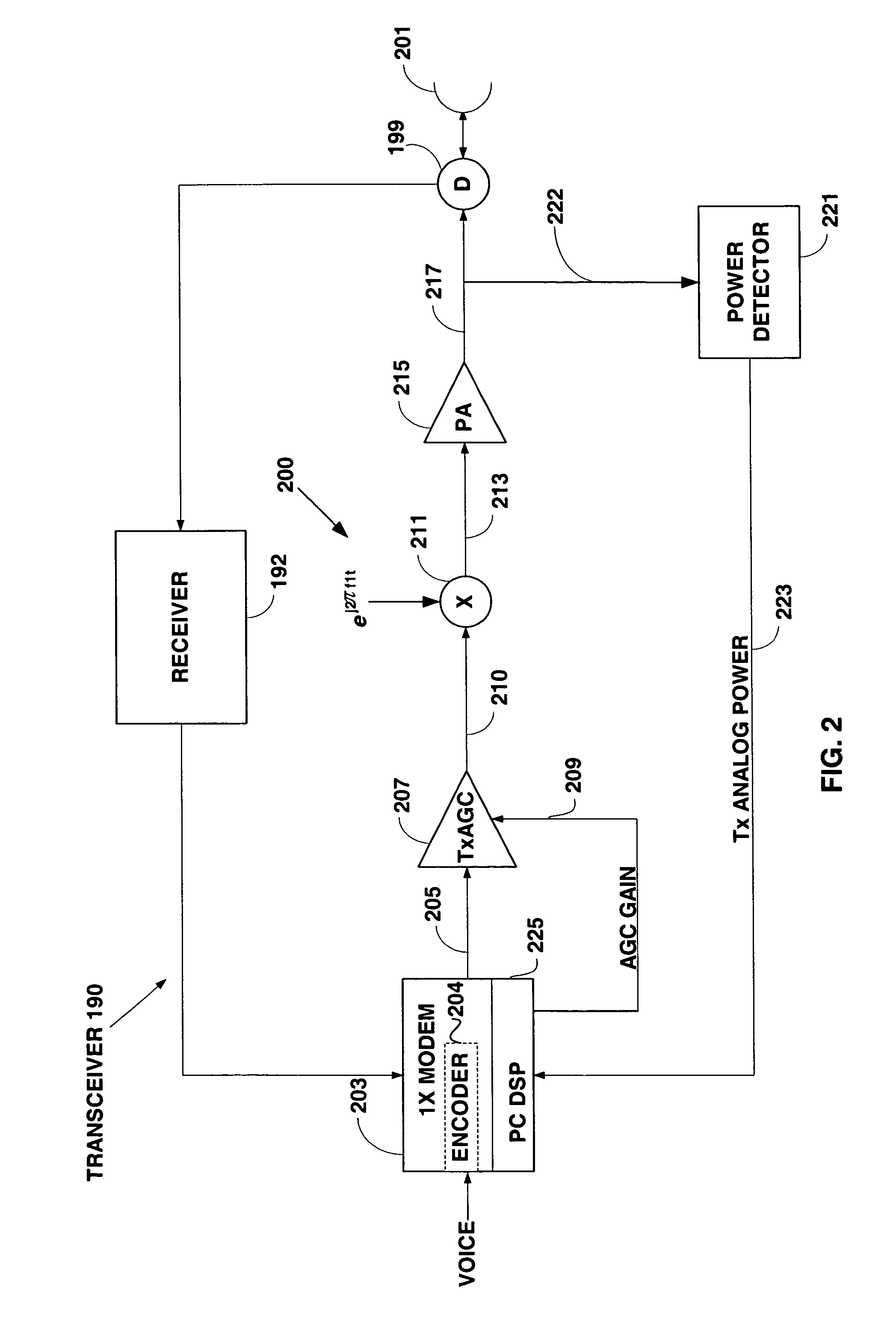
If a multi-carrier terminal has a single power amplifier for simultaneous transmission of different types of carrier signals, the power amplifier may be subject to power constraints imposed by spectral emission requirements, by on-board battery capacity, and also by any priority among the carriers.
Because the 1x carrier has priority over the DO carrier, the only power limitations imposed on the 1x carrier other than the peak power of the power amplifier are battery capacity and spectrum emission control schemes to limit the transmit power of mobile stations.

Method used


Image

  • Apparatus and method for prioritized apportionment of transmission power in a multi-carrier terminal
  • Apparatus and method for prioritized apportionment of transmission power in a multi-carrier terminal
  • Apparatus and method for prioritized apportionment of transmission power in a multi-carrier terminal

Examples


Embodiment Construction

[0016]The word “exemplary” is used herein to mean “serving as an example, instance, or illustration.” Any embodiment described herein as “exemplary” is not necessarily to be construed as preferred or advantageous over other embodiments. All of the embodiments described in this description are exemplary embodiments provided to enable persons skilled in the art to make or use the invention and not to limit the scope of the invention which is defined by the claims.

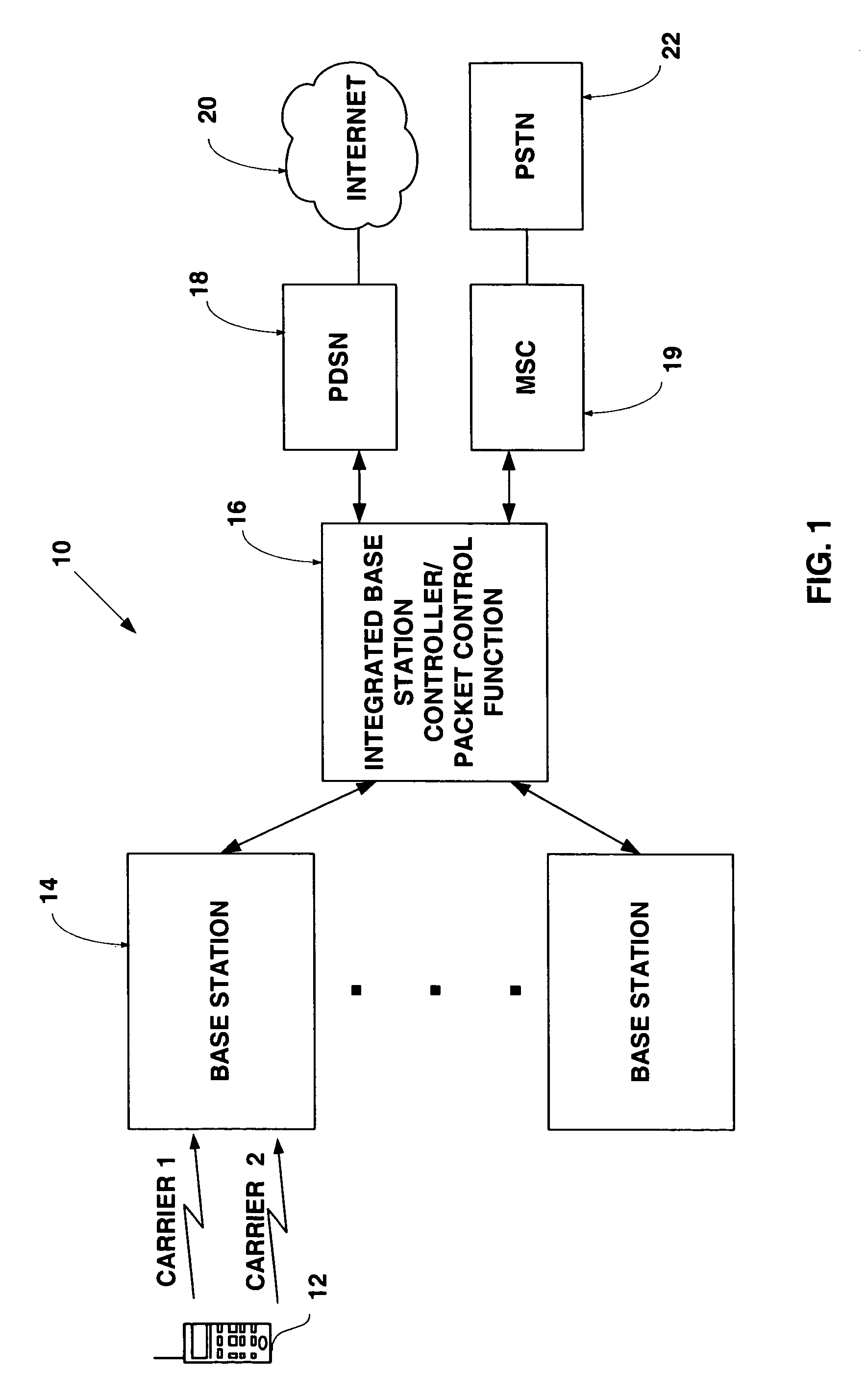
[0017]A subscriber station, referred to herein as an access terminal (AT), may be mobile or stationary, and may communicate with one or more base station transceivers (BTSs). An access terminal transmits and receives voice and data traffic through a base station transceiver subsystem coupled to a base station controller (BSC). Base station transceivers and base station controllers are parts of a network called an access network. An access network transports voice and data communications to and from multiple access terminals. ...


PUM


Abstract

In a multi-carrier access terminal having a transmitter with a single power amplifier, maximum transmission power available for a multi-carrier signal transmitted by the terminal is apportioned among a plurality of carriers on a priority basis. Following apportionment, the carriers are combined into a multi-carrier signal, amplified by the power amplifier and transmitted.

Description

BACKGROUND[0001]1. Field[0002]The present invention relates generally to telecommunications, and more specifically, to multi-carrier communications.[0003]2. Background[0004]In wireless communication systems, dual-carrier or multi-carrier terminals are increasingly being used for simultaneously carrying voice traffic and non-voice data traffic. In this regard, a multi-carrier terminal is a terminal having the capability of transmitting information on more than one carrier simultaneously. Many such terminals might be employed in a code division multiple access (CDMA) wireless communication system. For example, in an application requiring high-speed data and voice traffic to be transmitted simultaneously, it would be possible to use a multi-carrier terminal with one carrier supporting the CDMA2000—1x standard for voice traffic and another carrier supporting the CDMA2000—1xEv-DO standard, which is optimized for transmission of data traffic. The transmitting terminal would use one carrie...

Claims


Application Information

Patent Timeline
IPC IPC(8): H04B7/216H04B1/707H04B7/005H04J13/00H04L27/26H04L27/36
CPCH04L5/0044H04L27/2614H04L27/2637H04W52/52H04W52/30H04W52/343H04W52/346H04W52/281H04L27/26H04L27/36H04B7/005
Inventor MONTOJO, JUANBHUSHAN, NAGABLACK, PETER JOHN
Owner QUALCOMM INC
Learn More