Apparatus and methods for distributed temperature sensing

a technology of distributed temperature and sensors, applied in the direction of optical radiation measurement, instruments, spectrometry/spectrophotometry/monochromators, etc., can solve the problems of affecting the measurement signal and swamping the detector, so as to reduce the back-reflection of incident light

Inactive Publication Date: 2008-08-12
SCHLUMBERGER TECH CORP
View PDF3 Cites 18 Cited by
  • Summary
  • Abstract
  • Description
  • Claims
  • Application Information

AI Technical Summary

Benefits of technology

[0012]The coiled fibre portion, because it has no spatial length in the measurement direction, is effectively redundant as regards obtaining a temperature profile over the extent of the sensing fibre. However, light propagates along it, and it produces Raman backscatter, just as the remainder of the sensing fibre does. This backscatter will be detected at the fibre end, as usual, but if any saturation of the detector in the distributed temperature sensing (DTS) system occurs due to reflections from the immediately preceding reflective element, the backscatter from the coil will arrive at the detector while the detector is recovering its normal operation. Therefore, the disrupted part of the detected signal corresponds to light received from coil, which is not needed for the temperature profile. This part of the signal can hence be discarded with no loss of useful temperature data, allowing the disruption to be removed to leave a desired good quality profile over the length of the sensing fibre.
[0032]The optical fibre may be further comprised of one or more further optical fibre portions sequentially joined to the said two optical fibre portions by one or more joins comprising abutted end facets of adjacent optical fibre portions, each facet arranged at an angle to a longitudinal axis of the optical fibre to reduce back-reflection of incident light. The or each join may be implemented via an optical fibre connector.

Problems solved by technology

The sensing fibre may include several reflective elements which may all contribute to disrupting the measurement signal and swamping the detector.

Method used


Image

  • Apparatus and methods for distributed temperature sensing
  • Apparatus and methods for distributed temperature sensing
  • Apparatus and methods for distributed temperature sensing

Examples


first embodiment

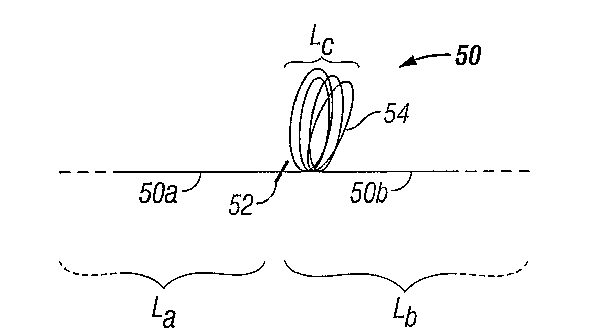
[0060]To address the problem of temperature measurements disrupted by Fresnel reflections, the present invention arranges a portion of coiled fibre in the sensing fibre immediately after the join, or other reflecting element, i.e. on the distal side of the reflecting element with respect to the forward probe pulse propagation direction. The length of the coiled portion is determined such that the time taken for light to propagate along it preferably matches or exceeds the length of time taken for the photodetector to recover from being overloaded by Fresnel reflections from the reflecting element. This will depend on the reflectivity of the element, which determines the amplitude of the Fresnel reflection, and on the recovery time of the photodetector after receiving a saturating signal of that amplitude.

[0061]FIG. 4A shows a portion of a sensing fibre according to this embodiment. The sensing fibre 50 comprises a proximal portion 50a having a length La and a distal portion 50b havi...


PUM

PropertyMeasurementUnit
lengthaaaaaaaaaa
lengthaaaaaaaaaa
lengthaaaaaaaaaa

Abstract

A sensing fibre for use in a distributed temperature sensing system comprises an optical fibre to be deployed in a measurement region in which a temperature measurement is to be made, which incorporates a reflective element, such as a join between portions of fibre, and a coiled fibre portion positioned adjacent a distal side of the reflective element, the coiled fibre portion contributing substantially nothing to the spatial extent of the optical fibre when deployed. In use, the effect of any forward propagating light incident on the reflective element that is returned for detection by the system, and which saturates the detector, can be eliminated by removing the part of the detected signal that corresponds to the coiled portion, after which the detector will have recovered. The remaining parts of the signal can be used to derive the distributed temperature profile since these parts represent the whole extent of the sensing fibre owing to the lack of spatial extent of the coil. Coils can be provided on both sides of the reflective element for double-ended temperature sensing techniques.

Description

BACKGROUND OF THE INVENTION[0001]1. Field of the Invention[0002]The present invention relates to apparatus for distributed temperature sensing, and methods of using the apparatus to perform distributed temperature sensing.[0003]2. Description of Related Art[0004]Distributed temperature sensing (DTS) is a temperature measurement technique that uses optical fibre as a temperature sensor, and exploits Raman scattering within the fibre to determine temperature. The technique is described in Dakin, J. P. et al.: “Distributed Optical Fibre Raman Temperature Sensor using a semiconductor light source and detector”; Electronics Letters 21, (1985), pp. 569-570, and UK Patent Application GB 2140554A. A sensing fibre is deployed in an environment of interest in which temperature is to be measured. A pulse of probe light, typically a high power pulse from a laser, is launched into the fibre and propagates therein. The light undergoes scattering within the fibre from which several signals result....

Claims


Application Information

Patent Timeline
Patent Type & Authority Patents(United States)
IPC IPC(8): G02B6/00G01K11/32
CPCG01K11/32
Inventor CHEN, YUEHUAHARTOG, ARTHUR H.
Owner SCHLUMBERGER TECH CORP
Why Eureka
Try Eureka