Antenna arrangement and mobile terminal device

a mobile terminal and antenna technology, applied in the field of antenna arrangement and division, can solve the problems of inflexible antenna arrangement, inability to achieve good physical size performance, and difficulty in arranging a single large antenna in the terminal or inside the covering frame, so as to reduce the damping in the front end of the terminal, the effect of small antenna volume and good performan

Active Publication Date: 2008-08-12
FLEXTRONICS SALES & MARKETING A P
View PDF12 Cites 10 Cited by
  • Summary
  • Abstract
  • Description
  • Claims
  • Application Information

AI Technical Summary

Benefits of technology

[0008]Objective of the invention is to accomplish an antenna arrangement optimally adapted for as many frequency bands as possible. The frequency bands between the different antennas are divided in a way that allows a relatively easy production of antennas and avoids the need to intentionally cover the frequency areas between RX and TX bands.
[0010]The idea behind the invention is to accomplish an antenna arrangement adaptable to a mobile terminal in a way that the frequency design of the arrangement takes into account, as optimally as possible, the bands located in different frequencies. This would make it possible to cover the frequency areas of as many networks as possible with as few antennas as possible, but still achieving a good performance level.
[0014]There are many advantages with an antenna arrangement corresponding to the invention. Antenna arrangement, in which the frequency bands have been arranged in advance optimally for each antenna so that the bands fill an optimal frequency area, makes it possible to achieve a smaller total volume for the antennas as well as good performance. In this way a terminal operating in various different networks and many different bands can be made small in size.
[0015]As an additional advantage, the damping in the front end of the terminal may be reduced. In connecting the signals to and from the antenna for example switches realized by MEMS (micro-electromechanical systems) technology, which occupy little space, may be used. The filters placed in the transmitter-receivers may be simple of structure. They can be designed for a narrow band because there is no need for many frequencies to pass through the filters mentioned.
[0016]If the terminal is for example of the WCDMA or US3G types (uses PCS band), use of duplexers in the terminal is avoided enabling a simpler structure for the device as well as smaller size and better performance. Isolation between the various receiver and transmitter antennas of the antenna arrangement relieves the filtering requirements of the filters, thus making the designing of antennas smoother and / or reducing the size of the antennas in the antenna arrangement.

Problems solved by technology

Placing a single large antenna in the terminal or inside the covering frame may be difficult or even impossible in practice.
With a single antenna it is not possible to achieve a good enough performance in relation to the physical size, in comparison with the multi-band devices using multiple optimised antennas.
This kind of antenna arrangement is not flexible because the amount of antennas is bound to the amount of frequencies.
In addition, since the circuitry of the antenna arrangement is fixed, the filter structure requires a relatively large quantity of filters.

Method used


Image

  • Antenna arrangement and mobile terminal device
  • Antenna arrangement and mobile terminal device
  • Antenna arrangement and mobile terminal device

Examples


Embodiment Construction

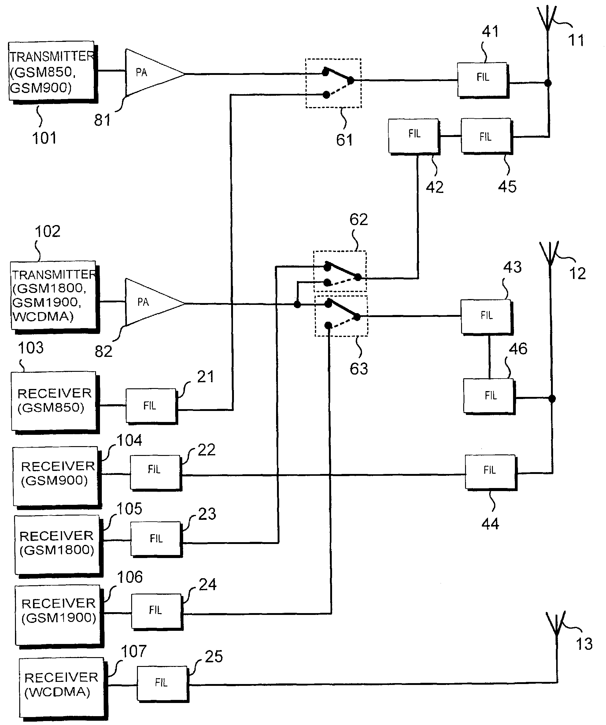
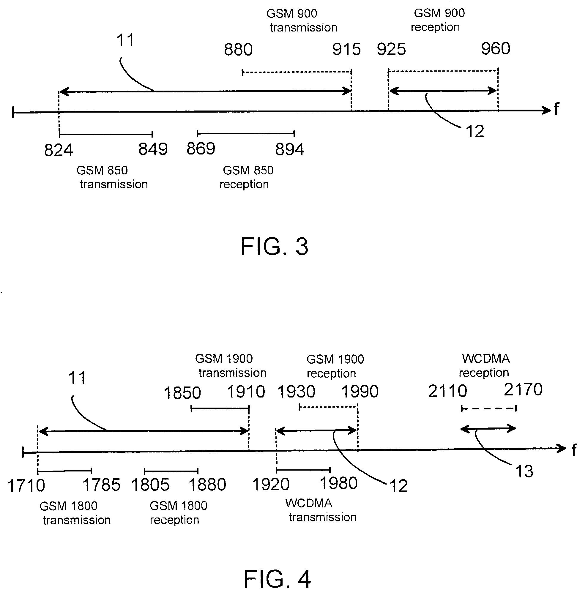
[0027]Antenna arrangement corresponding to the invention is suitable for usage in terminals and mobile stations using wireless data transfer. The objective is to cover as large a frequency area as possible with the new antenna arrangement described below, however in a way that keeps the quantity and physical volume of the antennas as small as possible, without affecting the performance. The antenna arrangement makes it possible for a terminal to operate in networks all over the world applying different frequency bands and technologies, as a so-called multi-band terminal.

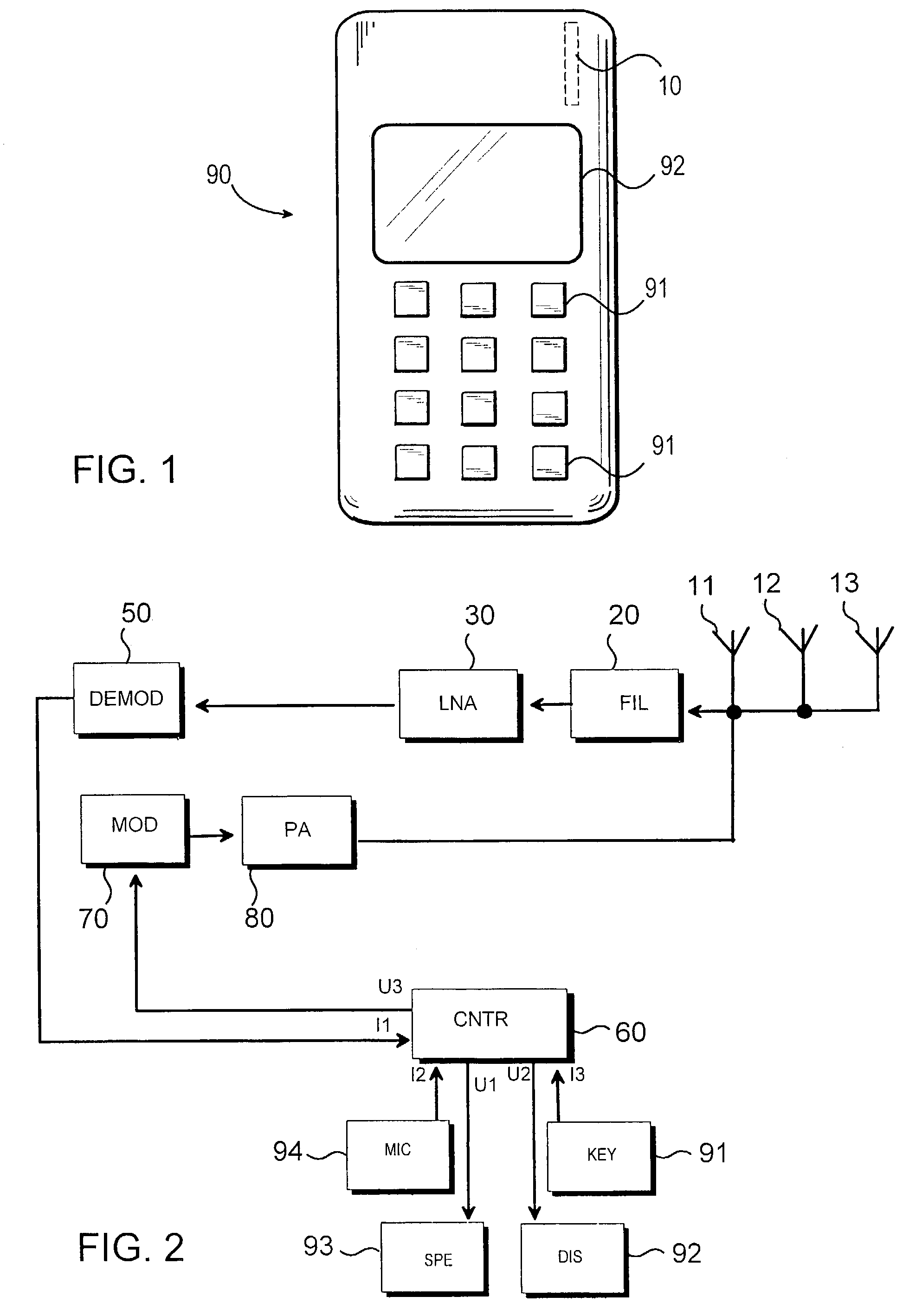
[0028]In the following we will review more closely, by referring to the FIG. 1-6, an implementation where the antenna arrangement is placed in a multi-band mobile station, which we will from now on just call mobile station or terminal. Type of the terminal used or location of the antenna arrangement in the terminal doesn't limit the invention.

[0029]FIG. 1 illustrates the location of antenna arrangement 10 in the mobi...


PUM


Abstract

The invention is concerned with an antenna arrangement adapted to a mobile terminal and division of frequency bands between different antennas. The antenna arrangement enables the terminal to operate worldwide in networks applying different frequency bands and technologies, as a so-called multi-band terminal. In the antenna arrangement the frequency bands of the antennas are arranged for each antenna in a way that the bands fill an optimal frequency area, thus accomplishing smaller total volume for the antennas and a good performance.

Description

FIELD OF THE INVENTION[0001]The invention relates antenna arrangement and division of the frequency bands that are transferred through it between different antennas. The invention is suitable for use in a subscriber terminal using wireless data transfer or in a mobile station such as mobile phone, for example.BACKGROUND OF THE INVENTION[0002]Nowadays there are available terminals that operate in various different frequency bands. Such terminals have greater performance and, in comparison with older terminals, are better adapted to take advantage of the new services appearing for the terminals all the time.[0003]Terminals adapted for multi-frequency usage may be utilized in those wireless communications networks where the operations have been adapted in advance to function together with the terminals.[0004]For each wireless communications system a previously determined frequency band is assigned for transmission and reception of signals. Wireless communications systems using differen...

Claims


Application Information

Patent Timeline
Patent Type & Authority Patents(United States)
IPC IPC(8): H04M1/00H04Q7/20H01QH01Q1/24H01Q5/00H01Q21/28H04B1/40H04B1/48H04B1/52H04Q7/32
CPCH01Q1/241H01Q21/28H04B1/52H04B1/48H04B1/005H04B1/40H01Q5/40
Inventor KLEMETTI, RAIMORAISANEN, KARIYLISIRNIO, JARKKOKOLANEN, SAMI
Owner FLEXTRONICS SALES & MARKETING A P
Why Eureka
Try Eureka