Device for a hot air shower

a technology for hot air showers and dryers, applied in lighting and heating apparatus, curling tongs, furnaces, etc., can solve problems such as unwanted cooling, and achieve the effect of simple construction and economic production

Inactive Publication Date: 2008-08-19
WELLA INT OPERATIONS SWITZERLAND SARL
View PDF5 Cites 118 Cited by
  • Summary
  • Abstract
  • Description
  • Claims
  • Application Information

AI Technical Summary

Benefits of technology

[0003]The object of the invention is therefore to create a device of this same generic type which does not have the aforementioned disadvantages and is simple in construction and can be produced economically.

Problems solved by technology

A disadvantage here is that the concentric cold-air stream simultaneously strikes the hair on the head as well, which leads to unwanted cooling.

Method used


Image

  • Device for a hot air shower
  • Device for a hot air shower
  • Device for a hot air shower

Examples


Embodiment Construction

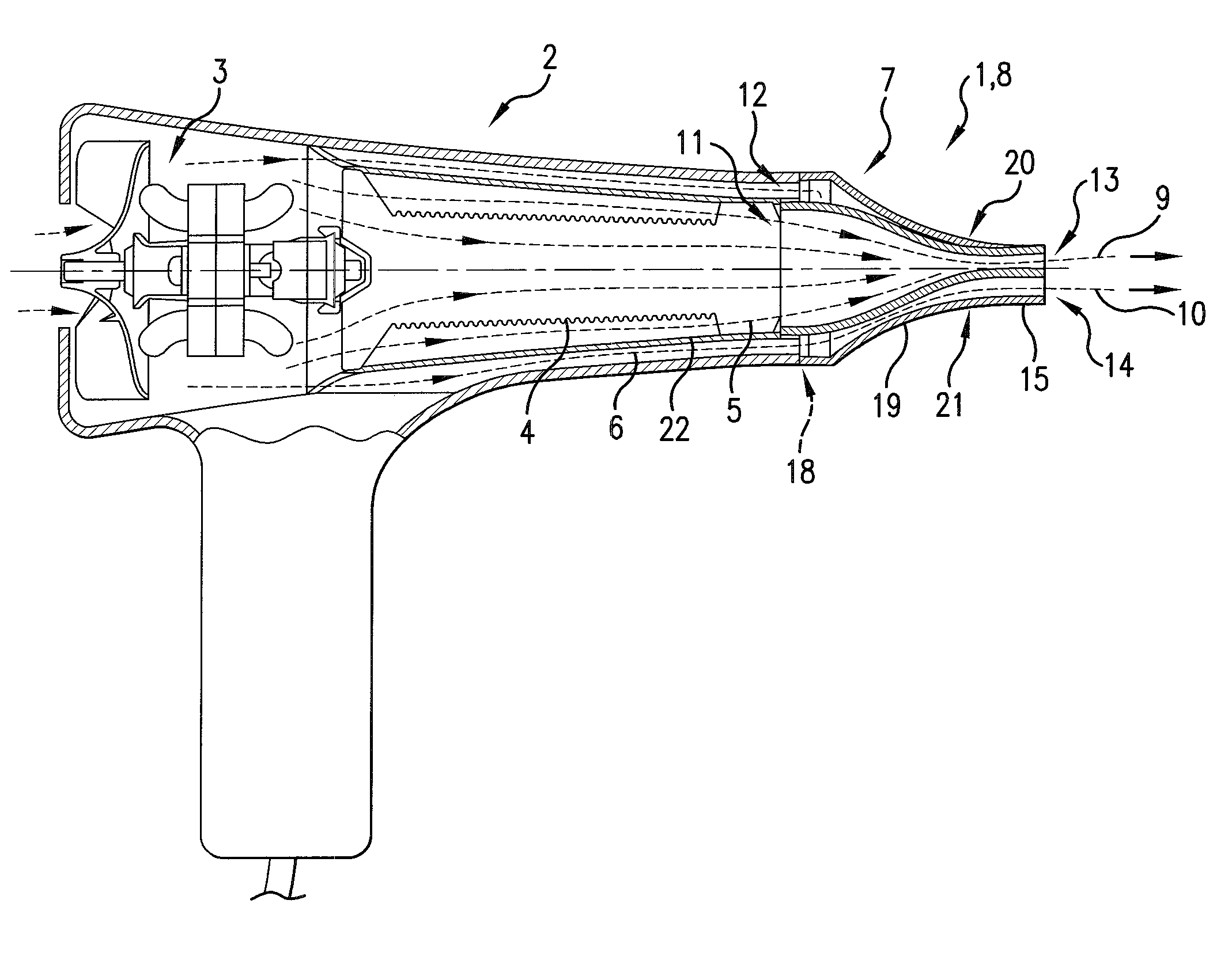
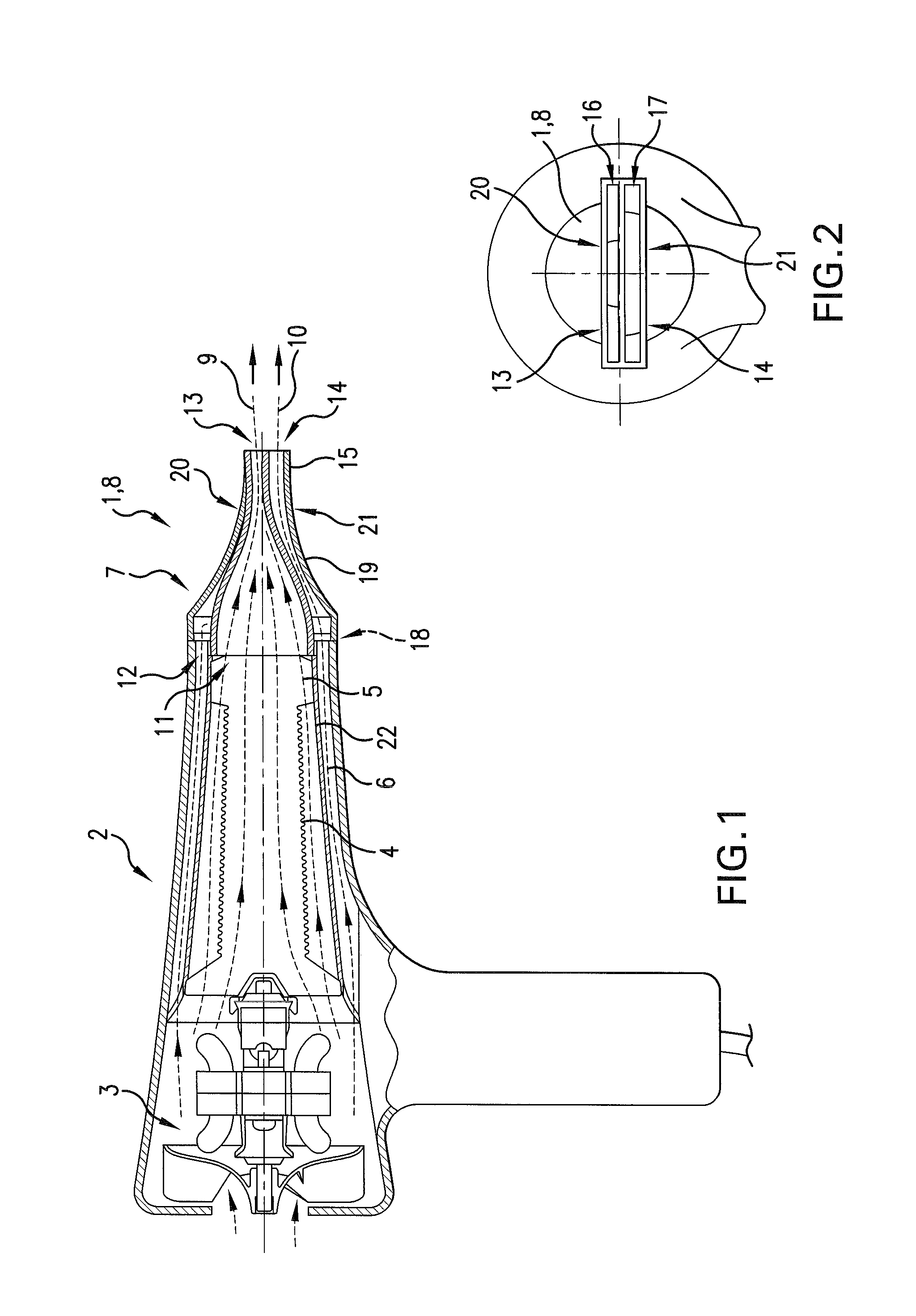
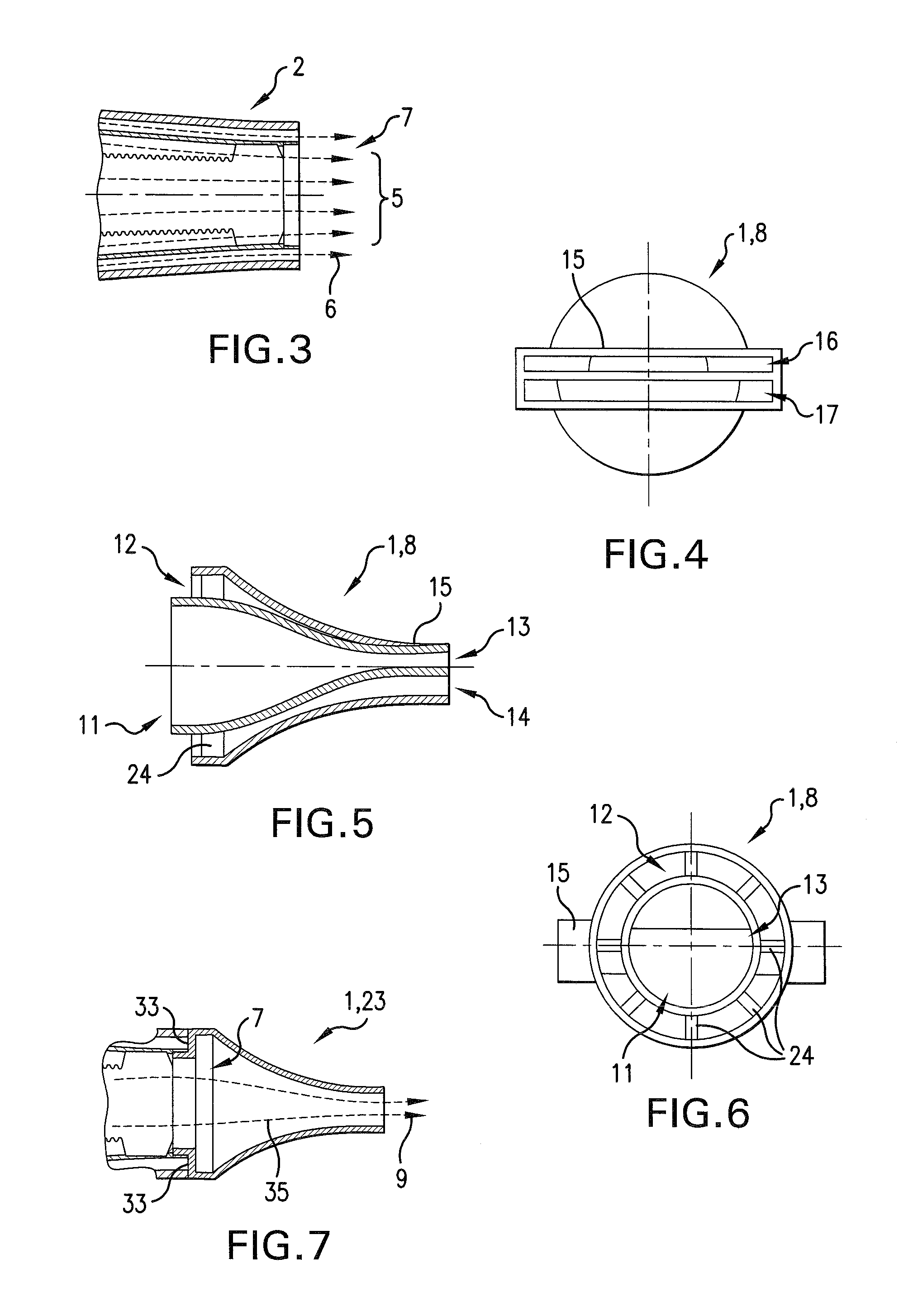
[0017]FIGS. 1 through 6 show a device 1 for a hair dryer 2, having a fan 3 and a heater 4 for generating a central hot-air stream 5 and a concentric cold-air stream 6 at a blower opening 7, and in the region of the heater 4, the hot-air stream 9 and the cold-air stream 10 are separated by a partition 22. As the device 1, an air nozzle attachment 8 embodied as connectable to the blower opening 7 is provided of a kind such that the air nozzle attachment 8, from the central hot-air stream 5 and the concentric cold-air stream 6 of the hair dryer 2, generates a hot-air stream 9 and a cold-air stream 10 that are located side by side. The air nozzle attachment 8, on the end with the blower opening 7, has a central conduit entrance 11 and a coaxial conduit entrance 12, and the central conduit entrance 11 discharges into a hot-air nozzle 13 and the coaxial conduit entrance 12 discharges into a cold-air nozzle 14, and the hot-air nozzle 13 and the cold-air nozzle 14 are located side by side. ...


PUM


Abstract

The air nozzle attachment (8) for the hair dryer (2) is connectable to the blower opening (7) of the hair dryer and produces a hot-air stream (9) and a cold-air stream (10) that are arranged side-by-side. The air nozzle attachment (8) has a hot-air nozzle (13) and a cold-air nozzle (14) located side-by-side and, on an end connectable to the blower opening (7), has a central conduit entrance (11) and a coaxial conduit entrance (12), which open into the hot-air nozzle (13) and the cold-air nozzle (14) respectively. The air nozzle attachment (8) can be detached again from the dryer (2) and preferably has a snap-on coupling device (18) for connecting the air nozzle attachment to the dryer (2), which permits rotation of the air nozzle attachment.

Description

BACK GROUND OF THE INVENTION[0001]The invention relates to a device for a hair dryer, having a fan and a heater, for generating a central hot-air stream and a concentric cold-air stream at a blower opening.[0002]A hair dryer of this kind, for instance for drying or otherwise treating hair on the head, is known for instance from German Utility Model DE9001199U1. In it, a concentric cold-air stream from a blower opening of a hair dryer is meant to prevent the scalp from becoming excessively hot from the hot-air stream. A disadvantage here is that the concentric cold-air stream simultaneously strikes the hair on the head as well, which leads to unwanted cooling.SUMMARY OF THE INVENTION[0003]The object of the invention is therefore to create a device of this same generic type which does not have the aforementioned disadvantages and is simple in construction and can be produced economically.[0004]This object and others, which will be made more apparent hereinafter, are attained in an air...

Claims


Application Information

Patent Timeline
Patent Type & Authority Patents(United States)
IPC IPC(8): A45D1/00A45D20/12F24H3/04
CPCF24H3/0423A45D20/12
Inventor MATTINGER, DETLEFSCHEUNERT, PETER
Owner WELLA INT OPERATIONS SWITZERLAND SARL
Why Eureka
Try Eureka