
Free-standing flying insect trap with removable cartridge

Active Publication Date: 2008-08-19
STERLING INT
View PDF31 Cites 80 Cited by
  • Summary
  • Abstract
  • Description
  • Claims
  • Application Information

AI Technical Summary

Benefits of technology

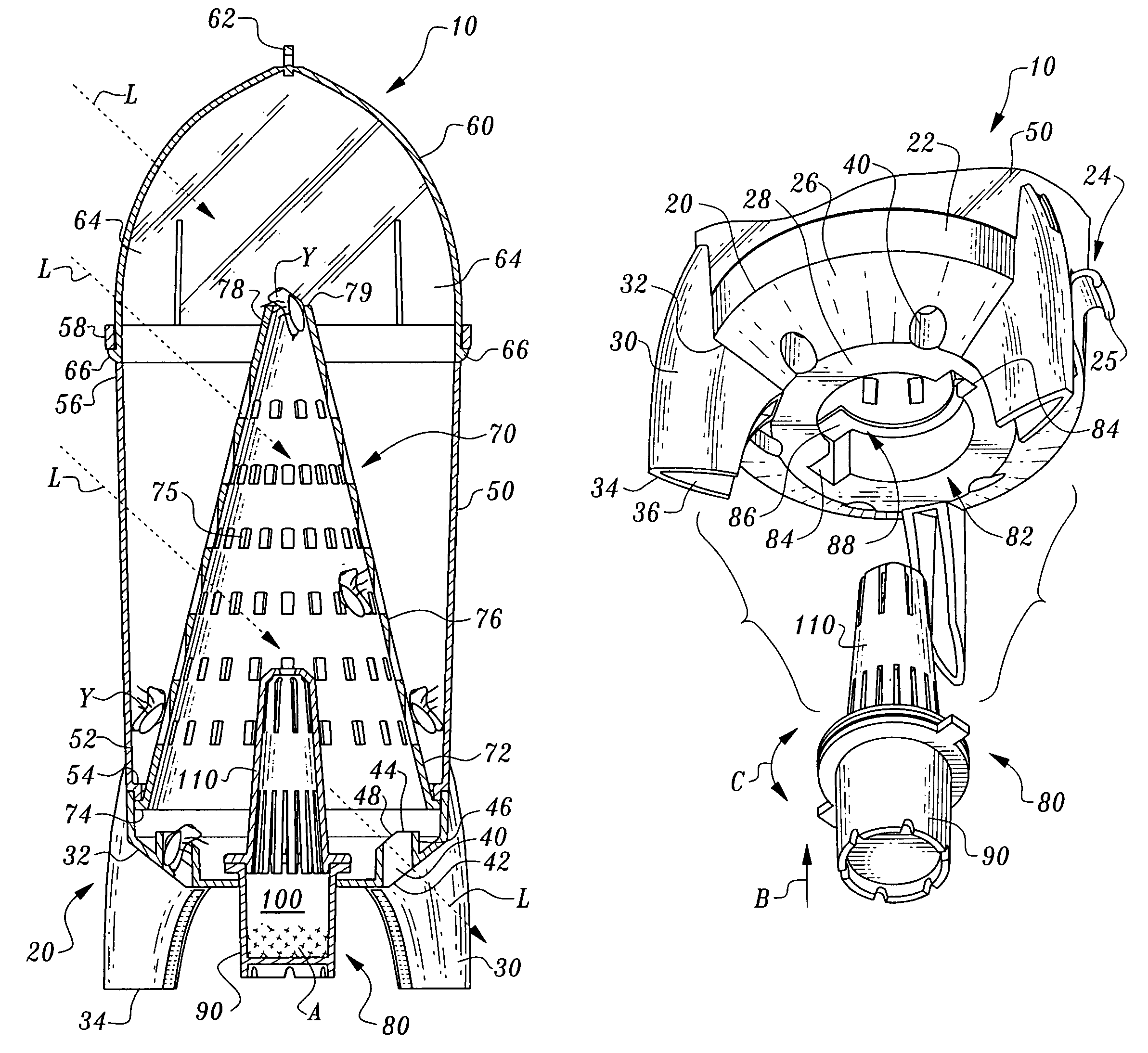
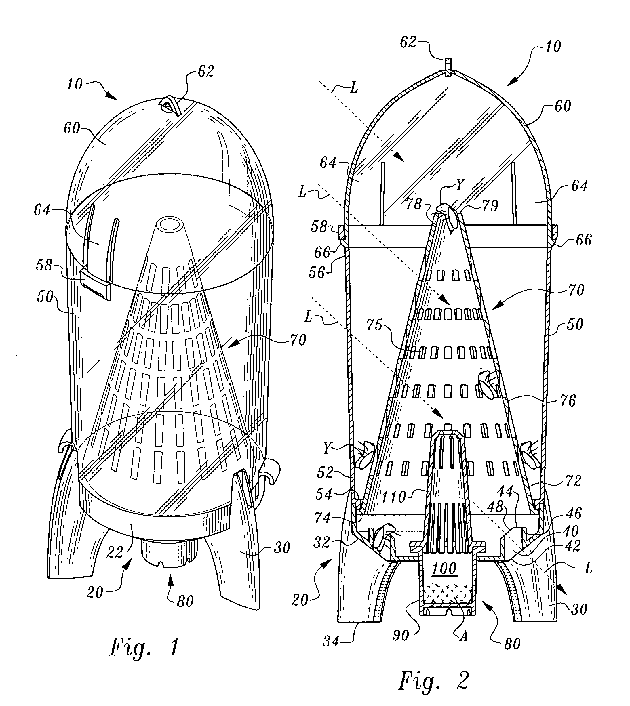
[0010]The enclosure is provided with entry holes which allow the flying insects or other pests to pass into the first chamber of the enclosure on the inner side of the funnel. These entry holes are preferably oriented so that they can be seen by a flying insect or other pest viewing the trap from the side. It has been discovered that many pests, particularly flying insects, do much of their navigation visually and have a preference for approaching an object such as the trap from a lateral direction. Hence, providing the entry holes at least partially visible from a lateral side of the trap increases the probability that the pests, and particularly flying insects such as yellowjackets, to find the entry holes and pass into the first chamber of the enclosure.
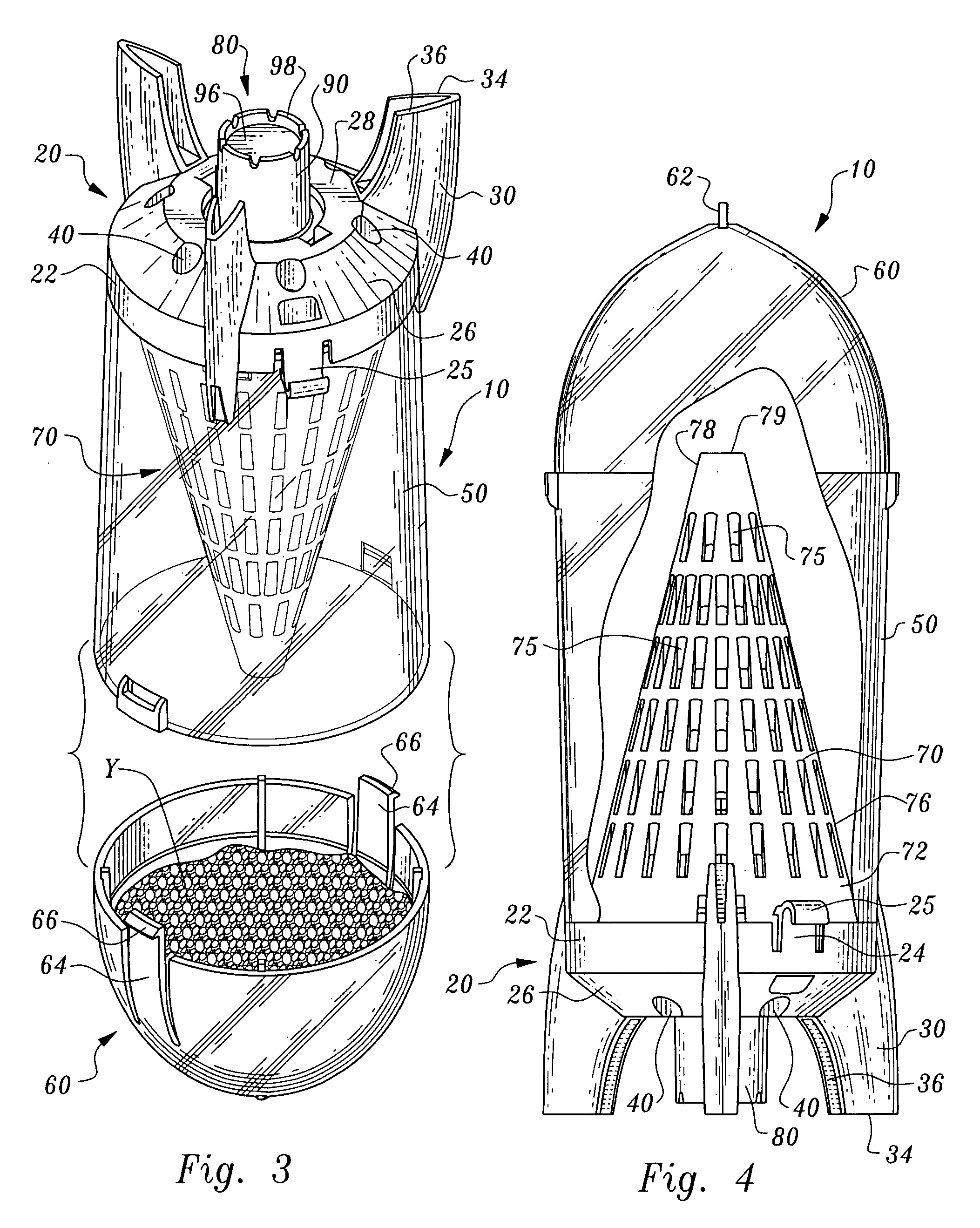
[0012]Most preferably, an attractant is provided which disperses into the air and has an aroma which is attractive to the pests to be trapped. This attractant is placed into the interior of the outer enclosure so that the aroma of the attractant passes through the entry holes to draw the pests through the entry holes and into the trap. Most preferably, the attractant is provided within a cartridge which is removably attachable to a portion of the enclosure of the trap. In this way, when the attractant has become depleted, the attractant cartridge can be removed and a new attractant cartridge provided in its place (or the original cartridge refilled) so that the ability of the trap to attract insects is maintained.
[0014]The trap is preferably provided with legs which allow the trap to rest upon an underlying generally horizontal surface. The trap can also optionally include an eyelet at an upper end of the trap so that the trap can alternatively be suspended from above. In a preferred embodiment, the legs are provided generally in the form of fins and the enclosure and fins together have a form generally similar to that of a rocket. In this way, the entire trap has the attractive and interesting appearance of a rocket, making it more desirable for users to display the trap without conveying the immediate message to visitors that pests might be present.OBJECTS OF THE INVENTION
[0018]Another object of the present invention is to provide a trap for flying insects which can be emptied and reused when full.
[0020]Another object of the present invention is to provide a trap for flying insects which is highly effective in drawing the flying insects to the trap and highly effective in trapping the insects therein.
[0021]Another object of the present invention is to provide a trap for flying insects which exhibits an extended life beyond a period for which an attractant material remains active and beyond a period it takes for the trap to fill up with trapped pests.

Problems solved by technology

Insects become trapped within the devices and die by either drowning (in a water-filled trap) or by dehydration and starvation (in a non-water filled trap).
Once insects have passed through the smaller aperture of the inverted cone, they become trapped in the uppermost section of the trap and later die of dehydration or starvation.
Thus, insects move through the smaller hole at the top of the cone into the upper section of the trap, where they die of dehydration and / or starvation.
First, it cannot be placed on a table or other level surface.
Also, this design does not allow for entry of insects from the side of the trap.
Yellowjackets normally approach the trap from the sides, and have trouble finding their way into the trap.
A significant percentage of insects approaching the trap cannot find the entrance into the trap to reach the attractant.
However, airflow through the trap directs attractant to these airflow holes and not specifically to the entrance holes, thus confusing the insects.
Additionally, it is very difficult to empty the trap of dead insects, requiring that the user completely disassemble the trap in order to empty the upper chamber.
This is a clumsy operation and can result in wasp stings to the user, should there be live wasps remaining in the trap.

Method used


Image

  • Free-standing flying insect trap with removable cartridge
  • Free-standing flying insect trap with removable cartridge
  • Free-standing flying insect trap with removable cartridge

Examples


Embodiment Construction

[0033]Referring to the drawings, wherein like reference numerals represent like parts throughout the various drawing figures, reference numeral 10 is directed to a trap for capturing pests, and particularly configured to capture yellowjacket wasps Y or other flying insects. The trap 10 is configured to draw the yellowjackets Y or other pests into the trap 10 and hold the yellowjackets Y or other pests therein until they die, typically from dehydration. The trap 10 is configured so that trapped yellowjackets Y can be removed, such as when the trap 10 is full, so that the trap 10 can continue to be used. The trap 10 preferably utilizes an attractant A to draw the yellowjackets Y into the trap 10. This attractant A is preferably provided within a removable cartridge 80, so that when the attractant A is depleted, a new cartridge 80 can be substituted for the original cartridge 80 so that the attractant A is refreshed and the trap 10 is renewed to capture additional yellowjackets Y.

[0034...


PUM


Abstract

A trap is provided particularly for yellowjacket wasps. The trap includes an outer enclosure with a funnel therein dividing the enclosure into a first chamber and a second chamber. A tip of the funnel has an opening which allows yellowjackets to pass from the first chamber to a second chamber, where the yellowjackets become trapped. The enclosure includes legs which allow the trap to rest upon an underlying surface. Entry holes extend into the first chamber. These entry holes are at least partially visible from a side of the trap. A top cap preferably forms a portion of the second chamber and can be removably replaced so that trapped yellowjackets can be dumped and the trap reused. An attractant is provided within a cartridge which is removably attached through a port in the enclosure, so that the cartridge can be replaced when original attractant is depleted.

Description

CROSS-REFERENCE TO RELATED APPLICATIONS[0001]This application is a divisional of U.S. patent application Ser. No. 11 / 137, 983, filed on May 25, 2005 now abandoned. This application claims benefit under Title 35, United States Code § 119(e) of U.S. Provisional Application No. 60 / 574,297 filed on May 25, 2004.FIELD OF THE INVENTION[0002]The following invention relates to traps for catching pests, and particularly flying insects. More particularly, this invention relates to traps for catching flying insects which rely on having an outer enclosure with a funnel inside the enclosure which encourages certain flying insects, such as yellowjacket wasps, to migrate from an interior side of the funnel to an exterior side of the funnel and become trapped on the exterior side of the funnel after passing through an open tip of the funnel.BACKGROUND OF THE INVENTION[0003]Traps for yellowjacket wasps (Vespula species), are numerous. They take many shapes and configurations, but generally require a...

Claims


Application Information

Patent Timeline
IPC IPC(8): A01M1/02A01M1/10
CPCA01M1/02A01M1/106A01M2200/012
Inventor HISCOX, WILLIAM C.
Owner STERLING INT
Learn More