
Progressing cavity pump

a technology of protruding cavity and positive displacement, which is applied in the direction of rotary or oscillating piston engines, engine lubrication, rotary piston engines, etc., can solve the problems of insufficient gas compression, difficulty in controlling the leakage flow and pressure distribution, and mechanical damage risk, so as to avoid cavitation appearance, improve mechanical behavior and overall reliability, and improve hydraulic performance

Active Publication Date: 2008-08-19
PC MALL INC
View PDF12 Cites 16 Cited by
  • Summary
  • Abstract
  • Description
  • Claims
  • Application Information

AI Technical Summary

Benefits of technology

"The present invention provides an improved pump design that overcomes the limitations of existing pumps. The pump includes a helical rotor and stator with hydraulic regulation means to achieve internal recirculation of the pumped fluid. The hydraulic regulation means serve to control the behavior of the pump, as a function of the production characteristics. The pump has improved mechanical behavior and overall reliability, and can use more rigid materials for the stator to increase the speed of rotation and flow rate of the pump. The hydraulic regulation means are self-regulated and the recirculation flow rate compensates for the local pressure difference, leakage flow rate, and compression of gas contained in the cavity. The pump design allows for continuous hydraulic regulation along the pump and compensates for the compressed volume of the pumped fluid."

Problems solved by technology

In practice, it is difficult to control the leakage flow and the pressure distribution that it generates.
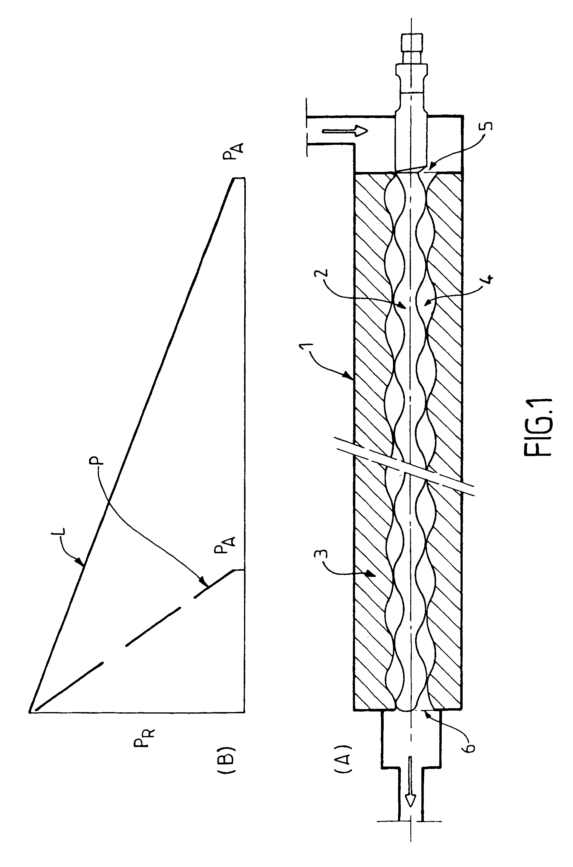
However, the annular leakage flow rate between the rotor 2 and the stator 3 of the PCP 1 is adapted to operating with a liquid (an incompressible fluid), for lubrication purposes at low flow rates; it is not sufficient to compensate for the compression of the gas.
The concentration of the pressures at the outlet of the pump and the large increase in the temperature gives rise to a risk of mechanical damage: degradation of the stator, mechanical expansion, and vibration.
Therefore, the concept of leakage via contact between the rotor and the stator, which concept is specific to the PCP, is unsuitable for pumping a compressible multi-phase mixture.
In general, the non-uniform pressure distribution along the PCP leads to excessive temperatures developing that jeopardize the reliability of the pump: degradation of the elastomer of the stator, dynamic instability of the rotor, and thermal forces and deformation of the structure.
Under such conditions, the outlet pressure must be limited and the speed of rotation of the pump must be reduced, thereby leading to degradation of pumped flow rates.
The appearance of cavitation is highly damaging to the strength of the elastomer stator and of the rotor, and thus to the reliability of the system.
Those solutions are effective only for a fixed proportion of gas and they are detrimental to operation with liquid.
In addition, those solutions cannot avoid the appearance of cavitation.
In addition, the modification of the architecture of the pump leads to a complex manufacturing process without guaranteeing good reliability.

Method used


Image

  • Progressing cavity pump
  • Progressing cavity pump
  • Progressing cavity pump

Examples


example 1

[0141]This test related to a prototype of a conventional PCP conveying a multi-phase mixture (water and air).

[0142]A PCP having thirteen stages (cavities) conveyed a multi-phase mixture delivering 50% water and 50% air, with an inlet pressure of 0.1 MPa (1 bar) and a pressure in the outlet duct of 4 MPa (40 bars), resulting in a gas compression ratio of 40 / 1. Because of the high compression ratio and because the leakage flow rate (between the rotor and the stator) was incapable of compensating for the compressed gas volume, the outlet pressure was achieved over the last four stages (cavities), resulting in a large pressure gain of 1 MPa (10 bars) per stage. All of the work of the pump was achieved by the last four stages, the remaining nine stages of the pump not contributing to compression of the mixture. That high compression concentrated on the last stages was accompanied by a large increase in temperature: the inlet temperature was multiplied by two.

[0143]Such high temperature a...

example 2

[0144]This test related to a prototype of a PCP improved with Hydraulic Regulators (HRs) and conveying a multi-phase mixture (water and air).

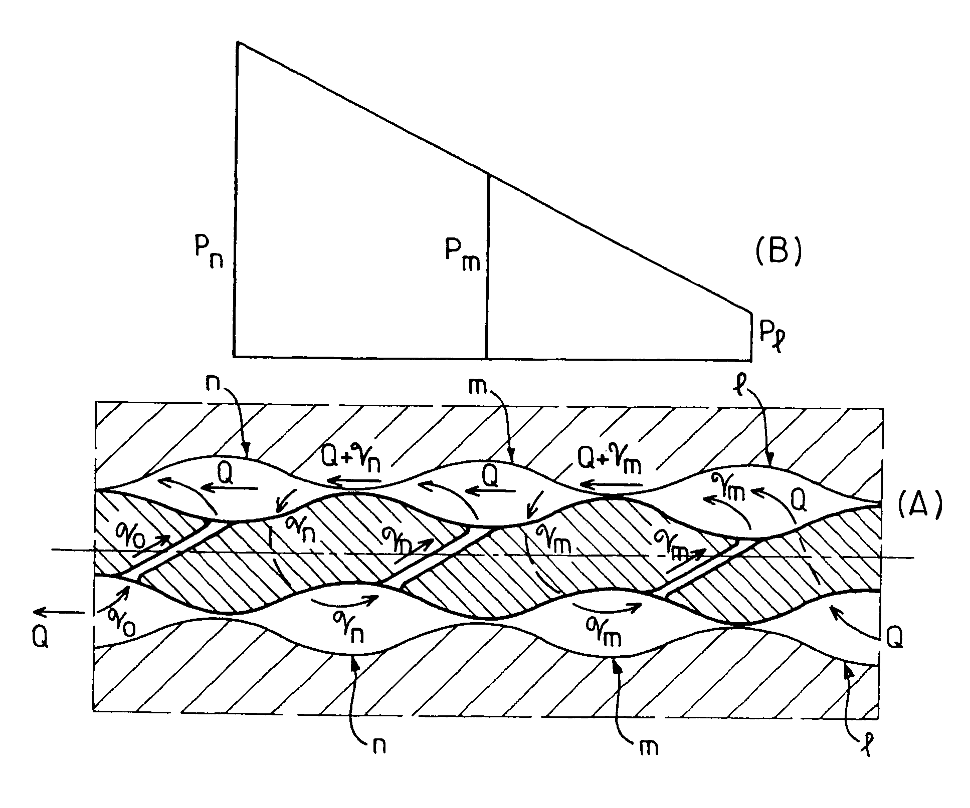
[0145]The pump of the present invention behaved quite differently; by means of the hydraulic regulators HRs installed in the rotor, the pressure distribution was rendered uniform, and the temperature was stabilized. Over the last four stages, the spread of hydraulic regulators HRs was two hydraulic regulators per stage and therefore the pressure gain was very small (about 0.1 MPa per stage). Over the remaining nine stages of the pump, the hydraulic regulators HRs were spread at one regulator HR per stage. Under these conditions, the pressure distribution was rendered uniform, resulting in a pressure gain of about 0.3 MPa (3 bars) per stage.

[0146]Therefore, rendering the pressure distribution along the pump uniform results in a small pressure gain for each stage, and in stabilization of the temperatures along the pump.

[0147]The variation in the ...

example 3

[0148]This test related to a prototype of a conventional PCP conveying a liquid (water).

[0149]The same PCP conveyed water with low pressure at the inlet (0.1 MPa (1 bar)) and a pressure of about 0.5 MPa in the outlet duct. Because of the dynamic behavior of the contact between the rotor and the stator, that pump developed very low pressures over stages 7 to 11, with a risk of cavitation.

[0150]Appearance of cavitation leads to damage of the materials, in particular the elastomer of the stator and the metal of the rotor.


PUM


Abstract

This progressing cavity pump includes a helical rotor (2) mounted to turn inside a helical stator (3). The stator (3) and the rotor (2) are disposed such that the cavities (4) formed therebetween move from the inlet (5) towards the outlet (6). In this cavity pump, hydraulic regulation (HR) means are provided for obtaining internal recirculation of the pumped fluid between at least two of the cavities (4) under conditions capable of performing at least one function selected from: achieving the desired pressure distribution along the pump, stabilizing the temperatures, controlling the leakage flow rates, and compensating for the volumes of compressed gas.

Description

FIELD OF THE INVENTION[0001]The present invention relates to improvements made to positive displacement pumps of the progressing cavity type, also known as “Moineau pumps”, and more specifically it relates to an improved positive displacement pump of the progressing cavity type, making it possible to pump single-phase or multi-phase mixtures or effluents of any viscosity, and in particular compressible multi-phase mixtures or effluents and fluids that are viscous to very viscous.[0002]The term “compressible multi-phase mixture or effluent” is used to mean a mixture of:[0003](a) a gas phase formed of at least one free gas; and[0004](b) a liquid phase formed of at least one liquid and / or[0005](c) a solid phase formed of the particles of at least one solid in suspension in (a) and, if phase (b) is present, in (a) and / or (b).[0006]However, as indicated above, the pump of the present invention naturally also makes it possible to pump a single phase or a liquid phase charged with solid pa...

Claims


Application Information

Patent Timeline
Patent Type & Authority Patents(United States)
IPC IPC(8): F04B49/00F01C1/10F04B35/04F04C2/08F04C2/107F04C13/00
CPCF04C2/086F04C2/1073F04C13/001F04C13/007F04C2/1075F04C2/084F04C2210/24
Inventor BRATU, CHRISTIAN
Owner PC MALL INC
Learn More